
Page 155 - Complete Wireless Design
P. 155
Amplifier Design
154 Chapter Three
requirements to attenuate output harmonics with high-Q matching in many
applications. Choosing the Q of the matching networks to be either high or
low will depend on whether the amplifier will be operated in a broadband
application. If it is, then the Q should be as low as possible in order to pass
as wide a band of frequencies as possible, while also enhancing the amplifi-
er’s stability. This stability should not be compromised if we do not allow the
matching network Q to exceed 5, even in designs for narrow bandwidths.
The physical PCB layout of power amplifiers must be carefully watched.
Excessively long emitter leads in a common-emitter amplifier can cause
degeneration—and instability in higher frequency applications—with the
effect of lower gain due to the added lead inductance. In Class C common-base
power amplifiers, the effects can be even more pronounced, and will rapidly
lead to complete instability.
Indeed, power amplifier stability can become an almost impossible task if
the transistor is operated significantly below its own power or frequency rat-
ing. This is due to the increased gain over a safe, stable value when the tran-
sistor is not operated closer to its design specifications.
Many power transistors today are protected against instant destruction
caused by brief intervals of mismatch and instability by modern fabrication
techniques. Protection is important, since instability oscillations will create
high peak voltages and collector currents, causing damage to an unprotected
device.
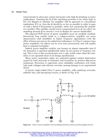
A typical single-ended Class C power amplifier, with matching networks,
collector bias, and decoupling circuits, is shown in Fig. 3.53.
Figure 3.53 Class C power amplifier with matching networks and bias and decoupling circuits.
Downloaded from Digital Engineering Library @ McGraw-Hill (www.digitalengineeringlibrary.com)
Copyright © 2004 The McGraw-Hill Companies. All rights reserved.
Any use is subject to the Terms of Use as given at the website.