
Page 48 - Computational Colour Science Using MATLAB
P. 48
CHROMATICITY DIAGRAMS 35
corrected. The majority of reflectance spectrophotometers that are commercially
available do not correct for the spectral bandpass of the instrument.
The ASTM tables of weights are available in hard copy or electronic form
from the ASTM web site http://www.astm.org.
4.6 Correction for spectral bandpass
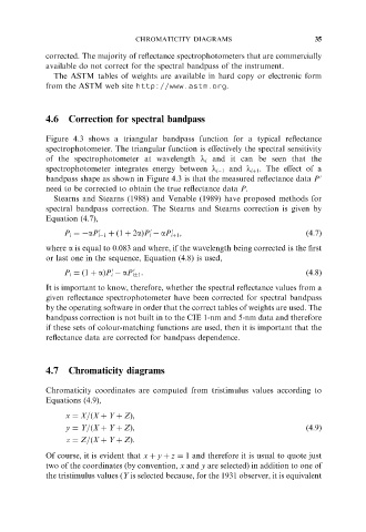
Figure 4.3 shows a triangular bandpass function for a typical reflectance
spectrophotometer. The triangular function is effectively the spectral sensitivity
of the spectrophotometer at wavelength l i and it can be seen that the
spectrophotometer integrates energy between l i 1 and l iþ1 . The effect of a
bandpass shape as shown in Figure 4.3 is that the measured reflectance data P 0
need to be corrected to obtain the true reflectance data P.
Stearns and Stearns (1988) and Venable (1989) have proposed methods for
spectral bandpass correction. The Stearns and Stearns correction is given by
Equation (4.7),
P i ¼ aP i 1 þð1 þ 2aÞP i aP iþ1 , ð4:7Þ
0
0
0
where a is equal to 0.083 and where, if the wavelength being corrected is the first
or last one in the sequence, Equation (4.8) is used,
P i ¼ð1 þ aÞP i aP i 1 . ð4:8Þ
0
0
It is important to know, therefore, whether the spectral reflectance values from a
given reflectance spectrophotometer have been corrected for spectral bandpass
by the operating software in order that the correct tables of weights are used. The
bandpass correction is not built in to the CIE 1-nm and 5-nm data and therefore
if these sets of colour-matching functions are used, then it is important that the
reflectance data are corrected for bandpass dependence.
4.7 Chromaticity diagrams
Chromaticity coordinates are computed from tristimulus values according to
Equations (4.9),
x ¼ X=ðX þ Y þ ZÞ,
y ¼ Y=ðX þ Y þ ZÞ, ð4:9Þ
z ¼ Z=ðX þ Y þ ZÞ.
Of course, it is evident that x þ y þ z ¼ 1 and therefore it is usual to quote just
two of the coordinates (by convention, x and y are selected) in addition to one of
the tristimulus values (Y is selected because, for the 1931 observer, it is equivalent