
Page 143 - Computational Modeling in Biomedical Engineering and Medical Physics
P. 143
132 Computational Modeling in Biomedical Engineering and Medical Physics
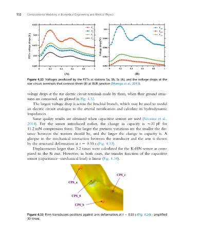
Figure 4.32 Voltages produced by the PZTs at stations Sa, Sb, Sc (A), and the voltage drops at the
star circuit terminals that connect them (B) at BUR junction (Morega et al., 2013).
voltage drops at the star electric circuit terminals made by them, when their ground arma-
tures are connected, are plotted in Fig. 4.32.
The largest voltage drop is across the brachial branch, which may be used to model
an electric circuit analogue to the arterial ramification and calculate its hydrodynamic
impedances.
Same quality results are obtained when capacitive sensors are used (Savastru et al.,
2014). For the sensor introduced earlier, the change in capacity is B31 pF for
11.2 mN compression force. The larger the pressure variations are the smaller the dis-
tance between the stations should be, and the larger the change in capacity is. A
glimpse in the mechanical interaction between the transducer and the arm is shown
by the structural deformation at t 5 0.55 s (Fig. 4.33).
Displacements larger than 3.2 times were calculated for the K-HN sensor as com-
pared to the Si one. However, in both cases, the transfer function of the capacitive
sensor (capacitance mechanical load) is linear (Fig. 4.34).
Figure 4.33 Firm transducers positions against arm deformation at t 5 0.55 s (Fig. 4.24)—amplified
30 times.