
Page 139 - Computational Modeling in Biomedical Engineering and Medical Physics
P. 139
128 Computational Modeling in Biomedical Engineering and Medical Physics
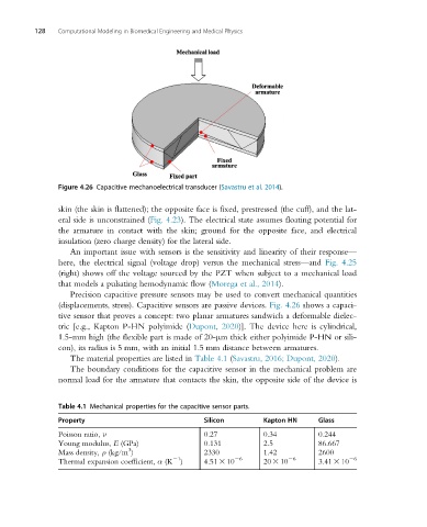
Figure 4.26 Capacitive mechanoelectrical transducer (Savastru et al. 2014).
skin (the skin is flattened); the opposite face is fixed, prestressed (the cuff), and the lat-
eral side is unconstrained (Fig. 4.23). The electrical state assumes floating potential for
the armature in contact with the skin; ground for the opposite face, and electrical
insulation (zero charge density) for the lateral side.
An important issue with sensors is the sensitivity and linearity of their response—
here, the electrical signal (voltage drop) versus the mechanical stress—and Fig. 4.25
(right) shows off the voltage sourced by the PZT when subject to a mechanical load
that models a pulsating hemodynamic flow (Morega et al., 2014).
Precision capacitive pressure sensors may be used to convert mechanical quantities
(displacements, stress). Capacitive sensors are passive devices. Fig. 4.26 shows a capaci-
tive sensor that proves a concept: two planar armatures sandwich a deformable dielec-
tric [e.g., Kapton P-HN polyimide (Dupont, 2020)]. The device here is cylindrical,
1.5-mm high (the flexible part is made of 20-μm thick either polyimide P-HN or sili-
con), its radius is 5 mm, with an initial 1.5 mm distance between armatures.
The material properties are listed in Table 4.1 (Savastru, 2016; Dupont, 2020).
The boundary conditions for the capacitive sensor in the mechanical problem are
normal load for the armature that contacts the skin, the opposite side of the device is
Table 4.1 Mechanical properties for the capacitive sensor parts.
Property Silicon Kapton HN Glass
Poisson ratio, ν 0.27 0.34 0.244
Young modulus, E (GPa) 0.131 2.5 86.667
3
Mass density, ρ (kg/m ) 2330 1.42 2600
21 26 26 26
Thermal expansion coefficient, α (K ) 4.51 3 10 20 3 10 3.41 3 10