
Page 138 - Computational Modeling in Biomedical Engineering and Medical Physics
P. 138
Electrical activity of the heart 127
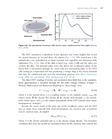
Figure 4.25 The piezoelectric transducer (left) and its output, nondimensional form (right) (Morega
et al., 2014).
The PZT transducers (cylindrical, 8-mm diameter and 2-mm height) that record
the arterial function are located above the arteries (Fig. 4.23). The central part is the
piezoelectric core, embedded in an elastic material, and capped by two aluminum disks
(armatures) (Fig. 4.25). One of the disks is fixed (e.g., with a cuff) and the other one
contacts the skin. The pressure pulse wave that drives the acceleration phase of the
blood flow is transmitted through the vessel wall and surrounding tissue to the PZT
cell, causing its compression and thus producing a voltage drop at the sensor terminals
that may be conditioned and used for monitoring purposes (Pro-Wave Electronics
Corp, 1998; Sur and Ghatak, 2020; Mohammadi et al., 2013).
The direct PZT coupling of electric and mechanical stress fields that, in the quasistatic,
linear approximation is described through the first-order Onsager relations (Chapter 1:
Physical, Mathematical and Numerical Modeling) in “stress-charge” form
T
σ 5 c E ε strain 2 e E; D 5 eε strain 1 ε 0 ε r E; ð4:26Þ
where σ is the normal stress, e is a coupling matrix, c E the elasticity matrix, ε strain the
relative strain, D the electric flux density, E the electric field strength, ε 0 the permit-
tivity of free space, and ε rS is the relative permittivity of the PZT material (here linear,
homogeneous, isotropic).
Because the sensor works at the pulse rate of the circulatory system and the PZT
uses an elastic linear material with small deformations, the electrical part of problem
may be assumed static, decoupled
2rðε 0 ε r rVÞ 5 ρ ;
v ð4:27Þ
where V is the electric potential and ρ V is the electric charge density. The boundary
conditions that close the model are mechanical stress for the armature that contacts the