
Page 114 -
P. 114
3.4 / BUS INTERCONNECTION 87
Bus
Boards
CPU
Memory
•
•
•
I/O
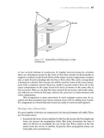
Figure 3.17 Typical Physical Realization of a Bus
Architecture
of two vertical columns of conductors. At regular intervals along the columns,
there are attachment points in the form of slots that extend out horizontally to
support a printed circuit board. Each of the major system components occupies
one or more boards and plugs into the bus at these slots. The entire arrangement
is housed in a chassis. This scheme can still be used for some of the buses associ-
ated with a computer system. However, modern systems tend to have all of the
major components on the same board with more elements on the same chip as
the processor. Thus, an on-chip bus may connect the processor and cache mem-
ory, whereas an on-board bus may connect the processor to main memory and
other components.
This arrangement is most convenient. A small computer system may be ac-
quired and then expanded later (more memory, more I/O) by adding more boards.
If a component on a board fails, that board can easily be removed and replaced.
Multiple-Bus Hierarchies
If a great number of devices are connected to the bus, performance will suffer.There
are two main causes:
1. In general, the more devices attached to the bus, the greater the bus length and
hence the greater the propagation delay. This delay determines the time it
takes for devices to coordinate the use of the bus. When control of the bus
passes from one device to another frequently, these propagation delays can
noticeably affect performance.