
Page 118 -
P. 118
3.4 / BUS INTERCONNECTION 91
may then initiate a data transfer (e.g., read or write) with some other device, which
acts as slave for this particular exchange.
TIMING Timing refers to the way in which events are coordinated on the bus. Buses
use either synchronous timing or asynchronous timing.
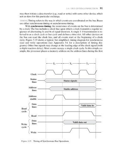
With synchronous timing, the occurrence of events on the bus is determined
by a clock.The bus includes a clock line upon which a clock transmits a regular se-
quence of alternating 1s and 0s of equal duration. A single 1–0 transmission is re-
ferred to as a clock cycle or bus cycle and defines a time slot. All other devices on
the bus can read the clock line, and all events start at the beginning of a clock
cycle. Figure 3.19 shows a typical, but simplified, timing diagram for synchronous
read and write operations (see Appendix 3A for a description of timing dia-
grams). Other bus signals may change at the leading edge of the clock signal (with
a slight reaction delay). Most events occupy a single clock cycle. In this simple ex-
ample, the processor places a memory address on the address lines during the first
T 1 T 2 T 3
Clock
Status
Status signals
lines
Address
Stable address
Stable address
lines
Address
enable
Data
Valid data in
lines
Read
cycle
Read
Data
Valid data out
Write lines
cycle
Write
Figure 3.19 Timing of Synchronous Bus Operations