
Page 127 -
P. 127
100 CHAPTER 3 / A TOP-LEVEL VIEW OF COMPUTER FUNCTION
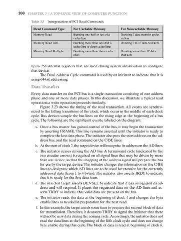
Table 3.5 Interpretation of PCI Read Commands
Read Command Type For Cachable Memory For Noncachable Memory
Memory Read Bursting one-half or less of a Bursting 2 data transfer cycles
cache line or less
Memory Read Line Bursting more than one-half a Bursting 3 to 12 data transfers
cache line to three cache lines
Memory Read Multiple Bursting more than three cache Bursting more than 12 data
lines transfers
up to 256 internal registers that are used during system initialization to configure
that device.
The Dual Address Cycle command is used by an initiator to indicate that it is
using 64-bit addressing.
Data Transfers
Every data transfer on the PCI bus is a single transaction consisting of one address
phase and one or more data phases. In this discussion, we illustrate a typical read
operation; a write operation proceeds similarly.
Figure 3.23 shows the timing of the read transaction. All events are synchro-
nized to the falling transitions of the clock, which occur in the middle of each clock
cycle. Bus devices sample the bus lines on the rising edge at the beginning of a bus
cycle.The following are the significant events, labeled on the diagram:
a. Once a bus master has gained control of the bus, it may begin the transaction
by asserting FRAME. This line remains asserted until the initiator is ready to
complete the last data phase.The initiator also puts the start address on the ad-
dress bus, and the read command on the C/BE lines.
b. At the start of clock 2,the target device will recognize its address on the AD lines.
c. The initiator ceases driving the AD bus. A turnaround cycle (indicated by the
two circular arrows) is required on all signal lines that may be driven by more
than one device, so that the dropping of the address signal will prepare the bus
for use by the target device.The initiator changes the information on the C/BE
lines to designate which AD lines are to be used for transfer for the currently
addressed data (from 1 to 4 bytes). The initiator also asserts IRDY to indicate
that it is ready for the first data item.
d. The selected target asserts DEVSEL to indicate that it has recognized its ad-
dress and will respond. It places the requested data on the AD lines and as-
serts TRDY to indicate that valid data are present on the bus.
e. The initiator reads the data at the beginning of clock 4 and changes the byte
enable lines as needed in preparation for the next read.
f. In this example, the target needs some time to prepare the second block of data
for transmission.Therefore, it deasserts TRDY to signal the initiator that there
will not be new data during the coming cycle.Accordingly, the initiator does not
read the data lines at the beginning of the fifth clock cycle and does not change
byte enable during that cycle.The block of data is read at beginning of clock 6.