
Page 202 -
P. 202
5.2 / ERROR CORRECTION 171
Table 5.2 Increase in Word Length with Error Correction
Single-Error Correction/
Single-Error Correction Double-Error Detection
Data Bits Check Bits % Increase Check Bits % Increase
8 4 50 5 62.5
16 5 31.25 6 37.5
32 6 18.75 7 21.875
64 7 10.94 8 12.5
128 8 6.25 9 7.03
256 9 3.52 10 3.91
This inequality gives the number of bits needed to correct a single bit error in a word
containing M data bits. For example, for a word of 8 data bits (M = 8), we have
• K = 3: 2 - 1 6 8 + 3
3
• K = 4: 2 - 1 7 8 + 4
4
Thus, eight data bits require four check bits.The first three columns of Table 5.2 lists
the number of check bits required for various data word lengths.
For convenience, we would like to generate a 4-bit syndrome for an 8-bit data
word with the following characteristics:
• If the syndrome contains all 0s, no error has been detected.
• If the syndrome contains one and only one bit set to 1, then an error has oc-
curred in one of the 4 check bits. No correction is needed.
• If the syndrome contains more than one bit set to 1, then the numerical value
of the syndrome indicates the position of the data bit in error. This data bit is
inverted for correction.
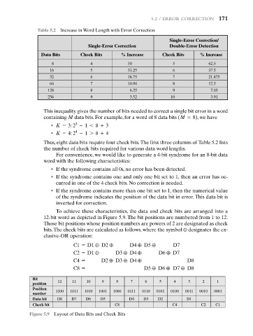
To achieve these characteristics, the data and check bits are arranged into a
12-bit word as depicted in Figure 5.9. The bit positions are numbered from 1 to 12.
Those bit positions whose position numbers are powers of 2 are designated as check
bits.The check bits are calculated as follows, where the symbol { designates the ex-
clusive-OR operation:
C1 = D1 { D2 { D4 { D5 { D7
C2 = D1 { D3 { D4 { D6 { D7
C4 = D2 { D3 { D4 { D8
C8 = D5 { D6 { D7 { D8
Bit
position 12 11 10 9 8 7 6 5 4 3 2 1
Position
number 1100 1011 1010 1001 1000 0111 0110 0101 0100 0011 0010 0001
Data bit D8 D7 D6 D5 D4 D3 D2 D1
Check bit C8 C4 C2 C1
Figure 5.9 Layout of Data Bits and Check Bits