
Page 367 - DSP Integrated Circuits
P. 367
352 Chapter 7 DSP System Design
(c) Schedule the operations over two sample intervals so that the number of
concurrent operations is minimized.
(d) Compare your result with the results obtained in Example 7.2.
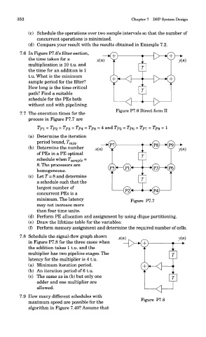
7.6 In Figure P7.6's filter section,
the time taken for a
multiplication is 10 t.u. and
the time for an addition is 1
t.u. What is the minimum
sample period for the filter?
How long is the time critical
path? Find a suitable
schedule for the PEs both
without and with pipelining.
Figure P7.6 Direct form II
7.7 The execution times for the
process in Figure P7.7 are
(a) Determine the iteration
period bound, T min. —KPT) T—Kps^-nS)—>
(b) Determine the number x(n) Y JL ^^ y y(n)
of PEs in a PE optimal fr]
schedule when T sampi e =
8. The processors are
@H—©H "—K?3^-KP6)
homogeneous.
I i |
(c) Let T = 8 and determine rj
a schedule such that the
largest number of
(P2> 1—*@
concurrent PEs is a
minimum. The latency Figure P7.7
may not increase more
than four time units.
(d) Perform PE allocation and assignment by using clique partitioning.
(e) Draw the lifetime table for the variables.
(f) Perform memory assignment and determine the required number of cells.
7.8 Schedule the signal-flow graph shown x(n) y(n)
in Figure P7.8 for the three cases when -D>X+) -j—•>
the addition takes 1 t.u. and the
multiplier has two pipeline stages. The |r
latency for the multiplier is 4 t.u.
(a) Minimum iteration period.
(b) An iteration period of 6 t.u. T
(c) The same as in (b) but only one \T
adder and one multiplier are
allowed.
7.9 How many different schedules with
Figure P7.8
maximum speed are possible for the
algorithm in Figure 7.40? Assume that