
Page 368 - DSP Integrated Circuits
P. 368
7.12 DCT Processor, Cont. 353
the algorithm is recursive—i.e., the output is fed back to one of the inputs of
one of the multiplications.
7.10 Introduce shimming delays into the structures shown in Figures 7.22 and
7.24.
7.11 (a) Show that the realizations shown in Figures 7.22 and 7.24 yield sample
frequencies corresponding to 3 and 2.5 clock cycles, respectively,
(b) Determine the required number of full-adders and D flip-flops in the
realization shown in Figure 7.21.
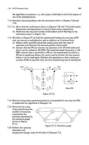
7.12 The filter in Figure P7.12 shall be implemented using only one type of PE
that can execute a multiplication and an addition as illustrated here.
(a) Define a fully specified signal-flow graph using only this type of
operation and that has the shortest possible critical path.
(b) Assume that the PE can execute one operation every 20 clock cycles and
that it can be clocked at 100 MHz. The required sample frequency is 1.25
MHz. Assume that a result from a PE can not immediately be used by a
PE due to pipelining. Hence, the result must be written into the memory
before it can be used again. Schedule the operations so that a minimum
number of PEs is required. Only one level of pipelining may be introduced.
Figure P7.12
7.13 Show by using clique partitioning that it is not possible to use only two PEs
to implement the algorithm in Example 7.8.
7.14 Determine by using
clique partitioning the
number of resources
required for the
processes described by
the exclusion graph
shown in Figure.
P7.14.
Figure P7.14 Exclusion graph
7.15 Perform the memory
allocation and
assignments design steps for the filter in Example 7.2.