
Page 370 - DSP Integrated Circuits
P. 370
7.12 DCT Processor, Cont. 355
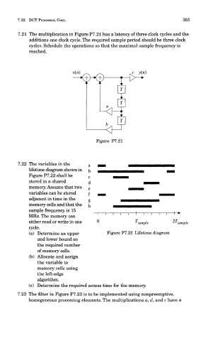
7.21 The multiplication in Figure P7.21 has a latency of three clock cycles and the
additions one clock cycle. The required sample period should be three clock
cycles. Schedule the operations so that the maximal sample frequency is
reached.
Figure P7.21
7.22 The variables in the
lifetime diagram shown in
Figure P7.22 shall be
stored in a shared
memory. Assume that two
variables can be stored
adjacent in time in the
memory cells and that the
sample frequency is 15
MHz. The memory can
either read or write in one
cycle.
(a) Determine an upper Figure P7.22 Lifetime diagram
and lower bound on
the required number
of memory cells.
(b) Allocate and assign
the variable to
memory cells using
the left-edge
algorithm.
(c) Determine the required access time for the memory.
7.23 The filter in Figure P7.23 is to be implemented using nonpreemptive,
homogeneous processing elements. The multiplications a, d, and e have a