
Page 410 - DSP Integrated Circuits
P. 410
9.4 Isomorphic Mapping of SFGs 395
The usefulness of this approach
depends to a high degree on the
type of arithmetic used in the PEs,
since there are many PEs. Parallel
arithmetic requires a large chip
area for the PEs. A more interesting
case is when bit-serial arithmetic is
used in the PEs. The advantage is
that PEs can easily be optimized for
chip area, speed, and work load.
Single-chip implementation is often
possible.
The major disadvantage of this
approach results from the fixed
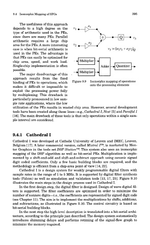
Figure 9.9 Isomorphic mapping of operations
binding of PEs to operations, which
onto the processing elements
makes it difficult or impossible to
exploit the processing power fully
by multiplexing. This drawback is
particularly pronounced in low sam-
ple rate applications, where the low
utilization of the PEs results in wasted chip area. However, several development
tools have been created along these lines—e.g., Cathedral I, Next [5] and Parsifal I
[16]. The main drawback of these tools is that only operations within a single sam-
ple interval are considered.
9.4.1 Cathedral I
Cathedral I was developed at Catholic University of Leuven and IMEC, Leuven,
Belgium [17]. A later commercial version, called Mistral 7™, is marketed by Men-
tor Graphics in the tools set DSP Station™. This system also uses an isomorphic
mapping of the DSP algorithm as well as bit-serial PEs. Multiplication is imple-
mented by a shift-and-add and shift-and-subtract approach using canonic signed
digit coded coefficients. Only a few basic building blocks are required, and the
methodology is efficient from a chip-area point of view [14, 22].
Cathedral I is a design system for weakly programmable digital filters with
sample rates in the range of 1 to 5 MHz. It is supported by digital filter synthesis
tools (Falcon) as well as simulation and validation tools [13, 17, 25]. Figure 9.10
illustrates the main steps in the design process used in Cathedral I.
In the first design step, the digital filter is designed. Design of wave digital fil-
ters is supported. The filter coefficients are optimized in order to minimize the
number of nonzero digits—i.e., the coefficients are represented by signed digit code
(see Chapter 11). The aim is to implement the multiplications by shifts, additions,
and subtractions, as illustrated in Figure 9.10. The control circuitry is based on
bit-serial building blocks.
In the next step the high-level description is translated into a bit-serial archi-
tecture, according to the principle just described. The design system automatically
introduces shimming delays and performs retiming of the signal-flow graph to
minimize the memory required.