
Page 408 - DSP Integrated Circuits
P. 408
9.3 Uniprocessor Architectures 393
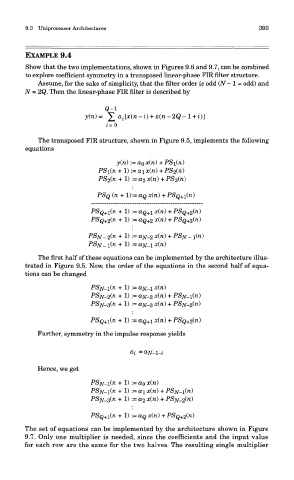
EXAMPLE 9.4
Show that the two implementations, shown in Figures 9.6 and 9.7, can be combined
to explore coefficient symmetry in a transposed linear-phase FIR filter structure.
Assume, for the sake of simplicity, that the filter order is odd (N — 1 = odd) and
N = 2Q. Then the linear-phase FIR filter is described by
The transposed FIR structure, shown in Figure 9.5, implements the following
equations
The first half of these equations can be implemented by the architecture illus-
trated in Figure 9.5. Now, the order of the equations in the second half of equa-
tions can be changed
Further, symmetry in the impulse response yields
Hence, we get
The set of equations can be implemented by the architecture shown in Figure
9.7. Only one multiplier is needed, since the coefficients and the input value
for each row are the same for the two halves. The resulting single multiplier