
Page 406 - DSP Integrated Circuits
P. 406
9.3 Uniprocessor Architectures 391
Input x(ri) x(n+l)
Mult. x(n - 3) x(n - 2) x(n - 1) x(n) x(n - 2) x(n -1) x(n) x(n+l)
Coeff. 03 02 GI OQ 03 02 #1 OQ
Part. Prod. p 3 p 2 pi Po PS Pz Pi PO
Output y(ri) y(n + 1)
Table 9.1 Operation of the FIR filter in Figure 9.4 with N = 4
Next, the remaining products in the convolution are successively computed
and accumulated. In the last time step y(ri) is obtained by adding the product ao
x(ri) to the accumulator register. Note that the input samples are written into the
memory position of the oldest input sample no longer needed.
EXAMPLE 9.2
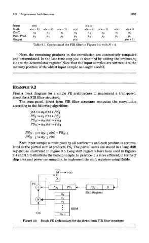
Find a block diagram for a single PE architecture to implement a transposed,
direct form FIR filter structure.
The transposed, direct form FIR filter structure computes the convolution
according to the following algorithm:
Each input sample is multiplied by all coefficients and each product is accumu-
lated as the partial sum of products, PSi. The partial sums are stored in a long shift
register, as illustrated in Figure 9.5. Long shift registers have been used in Figures
9.4 and 9.5 to illustrate the basic principle. In practice it is more efficient, in terms of
chip area and power consumption, to implement the shift registers using RAMs.
Figure 9.5 Single PE architecture for the direct form FIR filter structure