
Page 407 - DSP Integrated Circuits
P. 407
392 Chapter 9 Synthesis of DSP Architectures
EXAMPLE 9.3
Find a block diagram for a single PE architecture to implement transposed, direct
form FIR filter structures, but the generation of the partial sums should be gener-
ated in reverse order compared to the order used in Example 9.2.
The transposed, direct form FIR filter structure with partial sums computed
in reverse order is realized according to the following algorithm:
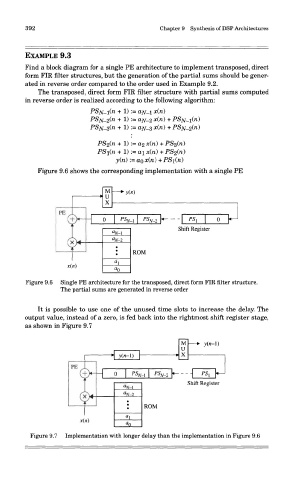
Figure 9.6 shows the corresponding implementation with a single PE
Figure 9.6 Single PE architecture for the transposed, direct form FIR filter structure.
The partial sums are generated in reverse order
It is possible to use one of the unused time slots to increase the delay. The
output value, instead of a zero, is fed back into the rightmost shift register stage,
as shown in Figure 9.7
Figure 9.7 Implementation with longer delay than the implementation in Figure 9.6