
Page 418 - DSP Integrated Circuits
P. 418
9.5 Implementations Based on Complex PEs 403
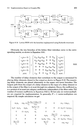
Figure 9.18 Lattice WDF with the branches implemented using Richards structures
Obviously, the two branches of the lattice filter introduce zeros in the corre-
sponding matrix, as shown in Equation (9.6).
The number of delay elements that contribute to the output is minimized by
placing delay elements closest to the output as shown in Figure 9.18. The remain-
ing delay elements are placed alternately in the upper and lower branches. The
longest path from the output of a delay element to the input of a delay element or
to the output of the filter is at most through two adaptors. Hence, the coefficient a y-
is a product of at most two adaptor coefficients; independent of the filter order. The
number of nonzero coefficients in Equation (9.6) is 19; but only six vector-multipli-
ers are required for implementation. In generally, N + 1 vector-multipliers are
required. By simple calculation we get