
Page 419 - DSP Integrated Circuits
P. 419
404 Chapter 9 Synthesis of DSP Architectures
Note that the adaptor coefficients have been optimized such that the number
of nonzero digits is minimized. However, in this approach the word lengths of the
coefficients appearing in the matrix should be minimized.
The numerically equivalent implementation has a minimum number of quan-
tization nodes and can be optimally scaled. If a low-sensitivity filter structure is
used, the roundoff noise will also be low. Hence, the total roundoff noise at the out-
put of the filter will be low and a short data word length can be used.
The coefficient word length can also be reduced by pipelining the original filter
structure. For example, lattice WDFs of the type shown in Figure 4.48 can be pipe-
lined by placing delay elements between the two sections. This reduces the coeffi-
cient word length as well as the number of input signals to the vector-multipliers at
the cost of two additional vector-multipliers to compute the values in the delay ele-
ment between the sections.
9.6 SHARED-MEMORY ARCHITECTURES WITH
BIT-SERIAL PEs
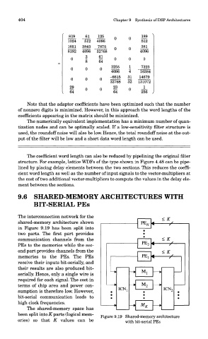
The interconnection network for the
shared-memory architecture shown
in Figure 9.19 has been split into
two parts. The first part provides
communication channels from the
PEs to the memories while the sec-
ond part provides channels from the
memories to the PEs. The PEs
receive their inputs bit-serially, and
their results are also produced bit-
serially. Hence, only a single wire is
required for each signal. The cost in
terms of chip area and power con-
sumption is therefore low. However,
bit-serial communication leads to
high clock frequencies.
The shared-memory space has
been split into K parts (logical mem-
Figure 9.19 Shared-memory architecture
ories) so that K values can be with bit-serial PEs