
Page 472 - DSP Integrated Circuits
P. 472
10.7 Finite State Machines (FSMs) 457
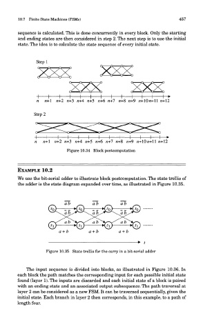
sequence is calculated. This is done concurrently in every block. Only the starting
and ending states are then considered in step 2. The next step is to use the initial
state. The idea is to calculate the state sequence of every initial state.
Figure 10.34 Block postcomputation
EXAMPLE 10.2
We use the bit-serial adder to illustrate block postcomputation. The state trellis of
the adder is the state diagram expanded over time, as illustrated in Figure 10.35.
Figure 10.35 State trellis for the carry in a bit-serial adder
The input sequence is divided into blocks, as illustrated in Figure 10.36. In
each block the path matches the corresponding input for each possible initial state
found (layer 1). The inputs are discarded and each initial state of a block is paired
with an ending state and an associated output subsequence. The path traversal at
layer 2 can be considered as a new FSM. It can be traversed sequentially, given the
initial state. Each branch in layer 2 then corresponds, in this example, to a path of
length four.