
Page 470 - DSP Integrated Circuits
P. 470
10.7 Finite State Machines (FSMs) 455
EXAMPLE 10.1
Use the look-ahead method to dou-
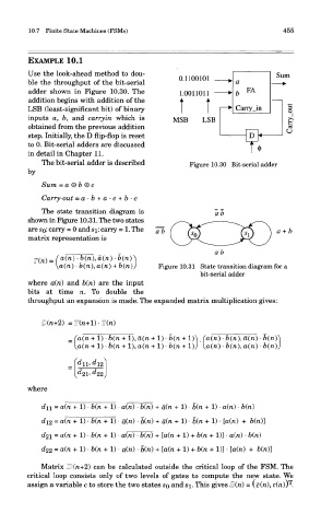
ble the throughput of the bit-serial
adder shown in Figure 10.30. The
addition begins with addition of the
LSB (least-significant bit) of binary
inputs a, b, and carry in which is
obtained from the previous addition
step. Initially, the D flip-flop is reset
to 0. Bit-serial adders are discussed
in detail in Chapter 11.
The bit-serial adder is described Figure 10.30 Bit-serial adder
by
Sum = a © b ® c
Carry-out = a-b + a-c + b-c
The state transition diagram is
shown in Figure 10.31. The two states
are SQ: carry = 0 and S]_: carry = 1. The
matrix representation is
Figure 10.31 State transition diagram for a
bit-serial adder
where a(n) and b(n) are the input
bits at time n. To double the
throughput an expansion is made. The expanded matrix multiplication gives:
where
Matrix Ii])(n+2) can be calculated outside the critical loop of the FSM. The
critical loop consists only of two levels of gates to compute the new state. We
T
assign a variable c to store the two states SQ and si. This gives S(n) = \c(n), c(n)) .