
Page 498 - DSP Integrated Circuits
P. 498
11.6 Bit-Serial Arithmetic 483
multiplier, a, is applied in a bit-parallel format. Many different schemes for bit-
serial multipliers have been proposed. They differ mainly in which order bit-prod-
ucts are generated and added and in the way subtraction is handled. A common
approach is to generate a row, or diagonal, of bit-products in each time slot (see
Figure 11.8) and perform the additions of the bit-products concurrently. We will in
this and the following sections describe several alternative serial/parallel multi-
plier algorithms and their implementations.
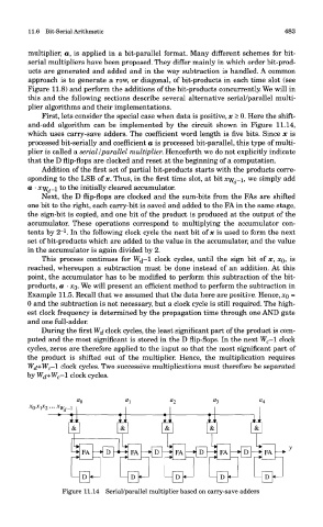
First, lets consider the special case when data is positive, x > 0. Here the shift-
and-add algorithm can be implemented by the circuit shown in Figure 11.14,
which uses carry-save adders. The coefficient word length is five bits. Since x is
processed bit-serially and coefficient a is processed bit-parallel, this type of multi-
plier is called a serial /parallel multiplier. Henceforth we do not explicitly indicate
that the D flip-flops are clocked and reset at the beginning of a computation.
Addition of the first set of partial bit-products starts with the products corre-
sponding to the LSB of x. Thus, in the first time slot, at bit xyf d_i, we simply add
a • xyf d_i to the initially cleared accumulator.
Next, the D flip-flops are clocked and the sum-bits from the FAs are shifted
one bit to the right, each carry-bit is saved and added to the FA in the same stage,
the sign-bit is copied, and one bit of the product is produced at the output of the
accumulator. These operations correspond to multiplying the accumulator con-
1
tents by 2" . In the following clock cycle the next bit of x is used to form the next
set of bit-products which are added to the value in the accumulator, and the value
in the accumulator is again divided by 2.
This process continues for W&-1 clock cycles, until the sign bit of x, XQ, is
reached, whereupon a subtraction must be done instead of an addition. At this
point, the accumulator has to be modified to perform this subtraction of the bit-
products, a • XQ. We will present an efficient method to perform the subtraction in
Example 11.5. Recall that we assumed that the data here are positive. Hence, XQ =
0 and the subtraction is not necessary, but a clock cycle is still required. The high-
est clock frequency is determined by the propagation time through one AND gate
and one full-adder.
During the first Wj clock cycles, the least significant part of the product is com-
puted and the most significant is stored in the D flip-flops. In the next W c—1 clock
cycles, zeros are therefore applied to the input so that the most significant part of
the product is shifted out of the multiplier. Hence, the multiplication requires
W^+Wc-1 clock cycles. Two successive multiplications must therefore be separated
by Wd+W c—l. clock cycles.
Figure 11.14 Serial/parallel multiplier based on carry-save adders