
Page 500 - DSP Integrated Circuits
P. 500
11.6 Bit-Serial Arithmetic 485
multiplications to increase the throughput. These serial/parallel multipliers,
using this technique, can be designed to perform one multiplication every
max{Wd, W c] clock cycles. A 16-bit serial/parallel multiplier implemented using
two-phase logic in a 0.8-um CMOS process requires an area of only 90 um x 550
2
um - 0.050 mm .
An alternative solution to copying the sign-bit in the first multiplier stage is
shown in Figure 11.16. The first stage, corresponding to the sign-bit in the coeffi-
cient, is replaced by a subtractor. In fact, only a half-adder is needed since one of the
inputs is zero. We will later see that this version is often the most favorable one.
Figure 11.16 Modified serial/parallel multiplier
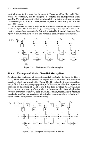
11.6.4 Transposed Serial/Parallel Multiplier
An alternative realization of the serial/parallell multiplier is shown in Figure
11.17, which adds the bit-products in Figure 11.6 columnwise. This multiplier
structure, which can be derived for Figure 11.16 by using the transposition theo-
rem, suffers from a long sum-propagation path. However, this disadvantage can be
alleviated by pipelining, at a cost of two D flip-flops per stage. An advantage is
that truncation or rounding of the product can be done so that the multiplication
time can be reduced to only Wj. clock cycles [26]. Further, this multiplier structure
can also be modified into a serial/serial multiplier, or squarer, where both the mul-
tiplier and the multiplicand arrive bit-serially.
Figure 11.17 Transposed serial/parallel multiplier