
Page 529 - DSP Integrated Circuits
P. 529
514 Chapter 11 Processing Elements
can therefore be loaded into the accumulators instead of being cleared
between two computations. A block diagram of the implementation is shown in
Figure 11.48.
To summarize, only two shift-accumulators are required to compute a complex
multiplication. A shift-accumulator is from area, speed, and power consumption
points of view comparable to a real serial/parallell multiplier.
(C + D) (C-D)
1 I
MUX
1
_ Add-Sub Shift-Accumulator Shift-Accumulator Add-Sub _
a
i H
Real part Imaginary part
AC-ED AD+BC
Figure 11.48 Block diagram for a complex multiplier using only two shift-
accumulators and a multiplexer
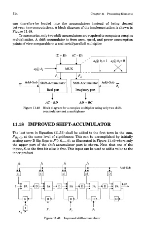
11.18 IMPROVED SHIFT-ACCUMULATOR
The last term in Equation (11.53) shall be added to the first term in the sum,
&
^Wd-l> t the same level of significance. This can be accomplished by initially
setting carry D flip-flops to F(Q, 0,..., 0), as illustrated in Figure 11.49 where only
the upper part of the shift-accumulator part is shown. Note that one of the
inputs, S, to the first bit-slice is free. This input can be used to add a value to the
inner product
Add-Sub
, t , , ,
rA i rA rA
1
* *
t I t t
1 1 i 1
F, Fo F-,
o t
Figure 11.49 Improved shift-accumulator