
Page 530 - DSP Integrated Circuits
P. 530
11.18 Improved Shift-Accumulator 515
11.18.1 Complex Multiplier Using Two-Phase Logic
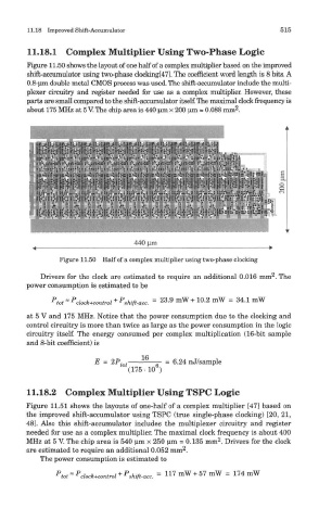
Figure 11.50 shows the layout of one half of a complex multiplier based on the improved
shift-accumulator using two-phase clocking[47]. The coefficient word length is 8 bits. A
0.8-um double metal CMOS process was used. The shift-accumulator include the multi-
plexer circuitry and register needed for use as a complex multiplier. However, these
parts are small compared to the shift-accumulator itself. The maximal clock frequency is
2
about 175 MHz at 5 V. The chip area is 440 urn x 200 urn = 0.088 mm .
Figure 11.50 Half of a complex multiplier using two-phase clocking
2
Drivers for the clock are estimated to require an additional 0.016 mm . The
power consumption is estimated to be
P P + P
tot~ clock +control shift-acc. = 23.9 mW + 10.2 mW = 34.1 mW
at 5 V and 175 MHz. Notice that the power consumption due to the clocking and
control circuitry is more than twice as large as the power consumption in the logic
circuitry itself. The energy consumed per complex multiplication (16-bit sample
and 8-bit coefficient) is
11.18.2 Complex Multiplier Using TSPC Logic
Figure 11.51 shows the layouts of one-half of a complex multiplier [47] based on
the improved shift-accumulator using TSPC (true single-phase clocking) [20, 21,
48]. Also this shift-accumulator includes the multiplexer circuitry and register
needed for use as a complex multiplier. The maximal clock frequency is about 400
2
MHz at 5 V. The chip area is 540 um x 250 urn = 0.135 mm . Drivers for the clock
2
are estimated to require an additional 0.052 mm .
The power consumption is estimated to