
Page 532 - DSP Integrated Circuits
P. 532
11.19 FFT Processor, Cont. 517
inlml
o
Start .... -* D D
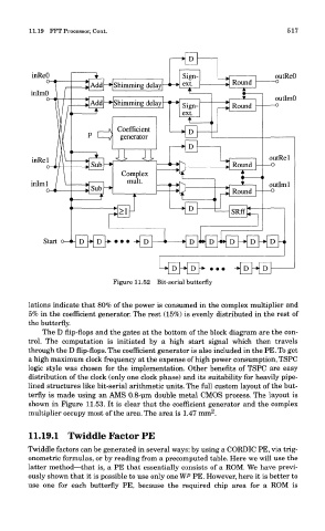
Figure 11.52 Bit-serial butterfly
lations indicate that 80% of the power is consumed in the complex multiplier and
5% in the coefficient generator. The rest (15%) is evenly distributed in the rest of
the butterfly.
The D flip-flops and the gates at the bottom of the block diagram are the con-
trol. The computation is initiated by a high start signal which then travels
through the D flip-flops. The coefficient generator is also included in the PE. To get
a high maximum clock frequency at the expense of high power consumption, TSPC
logic style was chosen for the implementation. Other benefits of TSPC are easy
distribution of the clock (only one clock phase) and its suitability for heavily pipe-
lined structures like bit-serial arithmetic units. The full custom layout of the but-
terfly is made using an AMS 0.8-um double metal CMOS process. The layout is
shown in Figure 11.53. It is clear that the coefficient generator and the complex
2
multiplier occupy most of the area. The area is 1.47 mm .
11.19.1 Twiddle Factor PE
Twiddle factors can be generated in several ways: by using a CORDIC PE, via trig-
onometric formulas, or by reading from a precomputed table. Here we will use the
latter method—that is, a PE that essentially consists of a ROM. We have previ-
ously shown that it is possible to use only one WP PE. However, here it is better to
use one for each butterfly PE, because the required chip area for a ROM is