
Page 536 - DSP Integrated Circuits
P. 536
11.19 FPT Processor, Cont. 521
tively. In k\ the bits denoted BF and N s are set to 0. Hence, the addresses are com-
puted by setting these bits to 1.
11.19.4 Base Index Generator
The base index generator must have three basic functions: a binary counter, a
Gray encoder, and a unit to compute P(ra). The counter can be implemented as a
bit-serial counter. This implementation requires a set of D flip-flops (a shift regis-
ter) and a bit-serial half-adder.
The translation of a binary number, x = x nx n_i--x\XQ, to its Gray coded equiv-
alent, y = y ny n-iyiyo, can be described by
© x • , -, if 0 < i < n
This operation can also be performed bit-serially. The computation of P(m) can
be described as
P(m) = (((...((m 0 )0m 1 )©m 2 )©m 3 )© ...)©m ?
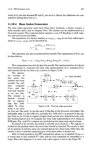
This computation can also be done bit-serially. The implementation of a device
that increments m, computes the Gray code representation of m, computes P(m),
and extends this by two bits to k\ is shown in Figure 11.56.
The genera-
tor consists of , [v^ m - Gary encoded
four parts: the
counter, the Gray
encoder, the unit
that computes D
P(ra), and the
unit that extends
— » ^ nut
m by two bits.
HA
The counter is
formed around
the m register
and the half-
adder. To incre- Figure 11.56 The base index generator
ment m by one's
we first use "Set carry" to set the carry D flip-flop of the bit-serial half-adder. The
half-adder adds 1 to the LSB of m, and thus the LSB of m+1 is present at the out-
put. Next we let 10 (the m register length) clock periods pass. Simultaneously with
the incrementation of m we compute the Gray code representation of m using an
XOR gate. The i and P(ra) outputs are used during the input and output phases.
To extend m by two bits, the switch is initially set to position 1. The register is
clocked to the position where the extra bits should be inserted. The switch is then
set to position 2 and two zeros are entered during two clock cycles. After this, the
switch is set to 3 and the remaining part of the base index is clocked out.
After 10 clock periods in the FFT computation phase, mg is checked. If mg = 1,
8
it means that m has reached 2 = 256, and we have computed all butterflies in a
stage. When this happens, m is reset, and a done signal is sent to the Stage PE.