
Page 144 - Defrosting for Air Source Heat Pump
P. 144
Investigation of effect on uneven defrosting performance 137
flowingalong the flow pathwouldbe reduced, and then the defrosting performance was
expected to be improved. However, at the same time, the total area of the circuit down-
side surface, or the total area of the remaining water, would increase exponentially,
from 2A in Fig. 5.14A, A two-circuit outdoor coil, to 3A in Fig. 5.14B, A three-circuit
outdoor coil, and then even to 4A in Fig. 5.14C, A four-circuit outdoor coil. The
remaining water would consume energy [26] and thus adversely affect the system
defrosting performance. Therefore, it is contradictory for the maximum flow path of
the melted frost and the total area of the remaining water on improving system
defrosting performance, when increasing circuit number of a fixed surface area
evaporator.
To solve this contradictory problem, the most effective method is to eliminate the
surface tension on the melted frost, and thus decrease the total area of remaining water.
Therefore, as a fundamental problem, the surface tension effects on melted frost, and
thus on the defrosting performance for an ASHP unit having a multicircuit outdoor
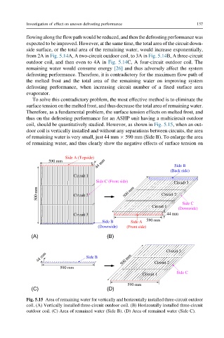
coil, should be quantitatively studied. However, as shown in Fig. 5.15, when an out-
door coil is vertically installed and without any separations between circuits, the area
of remaining water is very small, just 44 mm 590 mm (Side B). To enlarge the area
of remaining water, and thus clearly show the negative effects of surface tension on
Side A (Topside)
44 mm Side B
590 mm
(Back side)
Circuit 1
Side C (Front side) Circuit 3
mm 500 mm
500 Circuit 2 Circuit 2
Side C
Circuit 1
(Downside)
Circuit 3 44 mm
Side B Side A 590 mm
(Downside) (Front side)
(A) (B)
Circuit 3
44 mm Side B 500 mm
590 mm Circuit 2
Side C
Circuit 1
590 mm
(C) (D)
Fig. 5.15 Area of remaining water for vertically and horizontally installed three-circuit outdoor
coil. (A) Vertically installed three-circuit outdoor coil. (B) Horizontally installed three-circuit
outdoor coil. (C) Area of remained water (Side B). (D) Area of remained water (Side C).