
Page 147 - Defrosting for Air Source Heat Pump
P. 147
140 Defrosting for Air Source Heat Pump
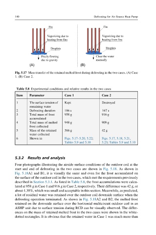
Fin Fin
Vaporizing due to Vaporizing due to
heating from fins heating from fins
Droplets Droplets
Freely flowing Clear the water
due to gravity manually
(A) (B)
Fig. 5.17 Mass transfer of the retained melted frost during defrosting in the two cases. (A) Case
1. (B) Case 2.
Table 5.8 Experimental conditions and relative results in the two cases
Item Parameter Case 1 Case 2
1 The surface tension of Kept Destroyed
remaining water
2 Defrosting duration 186 s 167 s
3 Total mass of frost 958 g 916 g
accumulated
4 Total mass of melted 948 g 909 g
frost collected
5 Mass of the retained 566 g 42 g
water collected
6 Shown in Figs. 5.17–5.20, 5.22; Figs. 5.17, 5.18, 5.21,
Tables 5.9 and 5.10 5.23; Tables 5.9 and 5.10
5.3.2 Results and analysis
Four photographs illustrating the airside surface conditions of the outdoor coil at the
start and end of defrosting in the two cases are shown in Fig. 5.18. As shown in
Fig. 5.18A1 and B1, it is visually the same and even for the frost accumulated on
the surface of the outdoor coil in the two cases, which met the requirements previously
described in Section 5.3.1. As listed in Table 5.8, the frost accumulations were calcu-
lated at 958 g in Case 1 and 916 g in Case 2, respectively. Their difference was 42 g, or
about 4.38%, which was small and acceptable in this section. Meanwhile, as predicted,
a lot of residual water was retained over the outdoor coil downside surface when the
defrosting operation terminated. As shown in Fig. 5.18A2 and B2, the melted frost
retained on the downside surface over the horizontal multicircuit outdoor coil in an
ASHP unit due to surface tension during RCD can be visually observed. The differ-
ences on the mass of retained melted frost in the two cases were shown in the white-
dotted rectangles. It is obvious that the retained water in Case 1 was much more than