
Page 212 - Defrosting for Air Source Heat Pump
P. 212
206 Defrosting for Air Source Heat Pump
Water collecting tray Water collecting tray
Melted Melted
R1 frost Circuit 1 Refrigerant (liquid) exit R1 frost Circuit 1 Refrigerant exit (liquid)
Melted
Melted
Refrigerant entrance (vapor) R2 Melted Circuit 2 Refrigerant entrance (vapor) R2 Melted Circuit 2
frost
frost
R3 frost Circuit 3 R3 frost Circuit 3
R1= R2= R3 R1 R2 R3
(A) (B)
Melted Melted
frost Circuit 1 Refrigerant exit (liquid) frost Circuit 1 Refrigerant exit (liquid)
Refrigerant entrance (vapor) R1 Melted Circuit 2 Refrigerant entrance (vapor) R1 Melted Circuit 2
frost
frost
R2
R2
Circuit 3
Circuit 3
R3
R3
R1= R2= R3 R1 R2 R3
(C) (D)
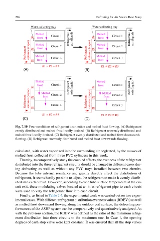
Fig. 7.10 Four conditions of refrigerant distribution and melted frost flowing. (A) Refrigerant
evenly distributed and melted frost locally drained. (B) Refrigerant unevenly distributed and
melted frost locally drained. (C) Refrigerant evenly distributed and melted frost downwards
flowing. (D) Refrigerant unevenly distributed and melted frost downwards flowing.
calculated, with water vaporized into the surrounding air neglected, by the masses of
melted frost collected from three PVC cylinders in this work.
Thereby, to comparatively study the coupled effects, the evenness of the refrigerant
distributed into the three refrigerant circuits should be changed in different cases dur-
ing defrosting as well as without any PVC trays installed between two circuits.
Because the tube internal resistance and gravity directly affect the distribution of
refrigerant, it seems hardly possible to adjust the refrigerant to make it evenly distrib-
uted into each circuit. However, according to each tube surface temperature at the cir-
cuit exit, these modulating valves located at an inlet refrigerant pipe to each circuit
were used to vary the refrigerant flow into each circuit.
Finally, as listed in Table 7.4, the experimental work was carried out on two exper-
imental cases. With different refrigerant distribution evenness values (RDEVs) as well
as melted frost downward flowing along the outdoor coil surface, the defrosting per-
formances of the ASHP system can be comparatively and quantitatively analyzed. As
with the previous section, the RDEV was defined as the ratio of the minimum refrig-
erant distribution into three circuits to the maximum one. In Case 1, the opening
degrees of each stop valve were kept constant. It was ensured that all the stop valves