
Page 214 - Defrosting for Air Source Heat Pump
P. 214
208 Defrosting for Air Source Heat Pump
refrigerant circuits. Meanwhile, when the stop valves are all fully open, the effects of
gravity and tube internal resistance on refrigerant distribution for a vertically installed
multicircuit outdoor coil could be found. This could be used for guiding to reach State
3 as well as analyzing the reason for the uneven frosting/defrosting phenomenon for an
ASHP unit. The detailed method was introduced in the previous section.
7.3.2 Experimental results
As shown in Table 7.5, the results of two experimental cases were listed, consisting of
the total mass of melted frost collected, the FECs at the start of RCD, and two
defrosting durations. The total masses of melted frost collected were nearly the same,
at 875 g in Case 1 and at 872 g in Case 2. Their FECs were 91.7% in Case 1 and 90.6%
in Case 2. Both of them were higher than 90%, with a difference of only 1.1%. Clearly,
frost accumulations on the three circuits in the two cases were both close to each other.
Their difference was smaller than 10%, which met the requirements described in the
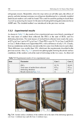
previous section. Also, Fig. 7.11 presents two photographs showing the airside surface
conditions of the outdoor coil at the start of defrosting in the two cases. As observed
Table 7.5 Experimental results of two experimental cases
Item Parameter Case 1 Case 2
1 FECs 91.7% 90.6%
2 Total mass of melted frost collected 875 g 872 g
3 Defrosting durations 185 s 173 s
4 Results shown in Figs. 7.11 A B
Fig. 7.11 Airside surface conditions of the outdoor coil at the start of the defrosting operation.
(A) Case 1 (without tray) and (B) Case 2 (without tray).