
Page 213 - Defrosting for Air Source Heat Pump
P. 213
The influence of refrigerant distribution on defrosting 207
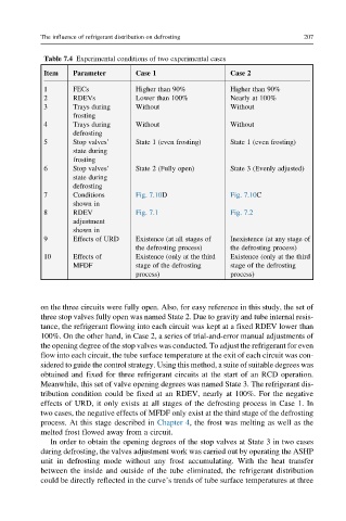
Table 7.4 Experimental conditions of two experimental cases
Item Parameter Case 1 Case 2
1 FECs Higher than 90% Higher than 90%
2 RDEVs Lower than 100% Nearly at 100%
3 Trays during Without Without
frosting
4 Trays during Without Without
defrosting
5 Stop valves’ State 1 (even frosting) State 1 (even frosting)
state during
frosting
6 Stop valves’ State 2 (Fully open) State 3 (Evenly adjusted)
state during
defrosting
7 Conditions Fig. 7.10D Fig. 7.10C
shown in
8 RDEV Fig. 7.1 Fig. 7.2
adjustment
shown in
9 Effects of URD Existence (at all stages of Inexistence (at any stage of
the defrosting process) the defrosting process)
10 Effects of Existence (only at the third Existence (only at the third
MFDF stage of the defrosting stage of the defrosting
process) process)
on the three circuits were fully open. Also, for easy reference in this study, the set of
three stop valves fully open was named State 2. Due to gravity and tube internal resis-
tance, the refrigerant flowing into each circuit was kept at a fixed RDEV lower than
100%. On the other hand, in Case 2, a series of trial-and-error manual adjustments of
the opening degree of the stop valves was conducted. To adjust the refrigerant for even
flow into each circuit, the tube surface temperature at the exit of each circuit was con-
sidered to guide the control strategy. Using this method, a suite of suitable degrees was
obtained and fixed for three refrigerant circuits at the start of an RCD operation.
Meanwhile, this set of valve opening degrees was named State 3. The refrigerant dis-
tribution condition could be fixed at an RDEV, nearly at 100%. For the negative
effects of URD, it only exists at all stages of the defrosting process in Case 1. In
two cases, the negative effects of MFDF only exist at the third stage of the defrosting
process. At this stage described in Chapter 4, the frost was melting as well as the
melted frost flowed away from a circuit.
In order to obtain the opening degrees of the stop valves at State 3 in two cases
during defrosting, the valves adjustment work was carried out by operating the ASHP
unit in defrosting mode without any frost accumulating. With the heat transfer
between the inside and outside of the tube eliminated, the refrigerant distribution
could be directly reflected in the curve’s trends of tube surface temperatures at three