
Page 222 - Defrosting for Air Source Heat Pump
P. 222
216 Defrosting for Air Source Heat Pump
7
Case 1
6
Case 2
5
Temperature ( o C) 4 3 T > T 2 T > T 1
1
2
T T T > T
2 1 2 2 1
90 s
1 60 s
26 s
0 40 80 120 160 200 240 280
Time (s)
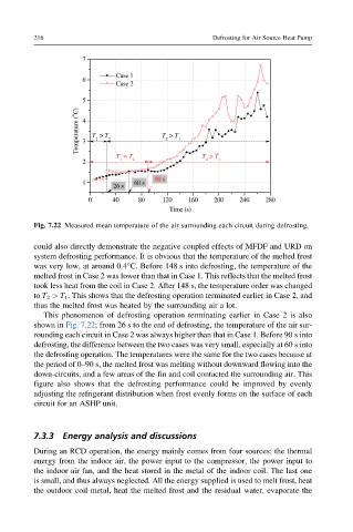
Fig. 7.22 Measured mean temperature of the air surrounding each circuit during defrosting.
could also directly demonstrate the negative coupled effects of MFDF and URD on
system defrosting performance. It is obvious that the temperature of the melted frost
was very low, at around 0.4°C. Before 148 s into defrosting, the temperature of the
melted frost in Case 2 was lower than that in Case 1. This reflects that the melted frost
took less heat from the coil in Case 2. After 148 s, the temperature order was changed
to T 2 > T 1 . This shows that the defrosting operation terminated earlier in Case 2, and
thus the melted frost was heated by the surrounding air a lot.
This phenomenon of defrosting operation terminating earlier in Case 2 is also
shown in Fig. 7.22; from 26 s to the end of defrosting, the temperature of the air sur-
rounding each circuit in Case 2 was always higher than that in Case 1. Before 90 s into
defrosting, the difference between the two cases was very small, especially at 60 s into
the defrosting operation. The temperatures were the same for the two cases because at
the period of 0–90 s, the melted frost was melting without downward flowing into the
down-circuits, and a few areas of the fin and coil contacted the surrounding air. This
figure also shows that the defrosting performance could be improved by evenly
adjusting the refrigerant distribution when frost evenly forms on the surface of each
circuit for an ASHP unit.
7.3.3 Energy analysis and discussions
During an RCD operation, the energy mainly comes from four sources: the thermal
energy from the indoor air, the power input to the compressor, the power input to
the indoor air fan, and the heat stored in the metal of the indoor coil. The last one
is small, and thus always neglected. All the energy supplied is used to melt frost, heat
the outdoor coil metal, heat the melted frost and the residual water, evaporate the