
Page 268 - Defrosting for Air Source Heat Pump
P. 268
262 Defrosting for Air Source Heat Pump
requirements of this study. Consequently, the system defrosting performances at dif-
ferent frost accumulations and with frost evenly distributed could be fully analyzed.
9.2.2 Experimental results and discussions
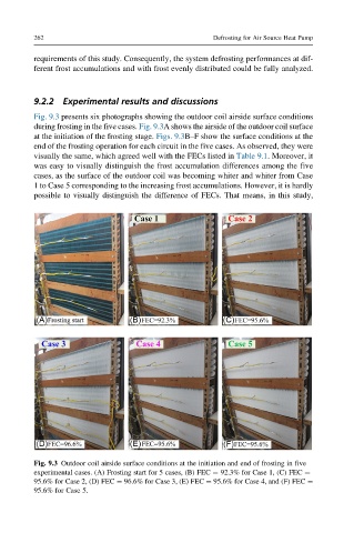
Fig. 9.3 presents six photographs showing the outdoor coil airside surface conditions
during frosting in the five cases. Fig. 9.3A shows the airside of the outdoor coil surface
at the initiation of the frosting stage. Figs. 9.3B–F show the surface conditions at the
end of the frosting operation for each circuit in the five cases. As observed, they were
visually the same, which agreed well with the FECs listed in Table 9.1. Moreover, it
was easy to visually distinguish the frost accumulation differences among the five
cases, as the surface of the outdoor coil was becoming whiter and whiter from Case
1 to Case 5 corresponding to the increasing frost accumulations. However, it is hardly
possible to visually distinguish the difference of FECs. That means, in this study,
Fig. 9.3 Outdoor coil airside surface conditions at the initiation and end of frosting in five
experimental cases. (A) Frosting start for 5 cases, (B) FEC ¼ 92.3% for Case 1, (C) FEC ¼
95.6% for Case 2, (D) FEC ¼ 96.6% for Case 3, (E) FEC ¼ 95.6% for Case 4, and (F) FEC ¼
95.6% for Case 5.