
Page 269 - Defrosting for Air Source Heat Pump
P. 269
Defrosting control strategy 263
calculating the FEC by adding water-collecting trays under each circuit is feasible and
meaningful.
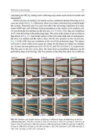
Fifteen pictures of outdoor coil airside surface conditions during defrosting in five
cases are shown in Fig. 9.4. Obviously, there is no water-collecting tray installed under
the circuits. Therefore, the five cases can reflect the defrosting conditions in a tradi-
tional ASHP unit, with different frost accumulating on the surface of the outdoor coil.
As seen from the five pictures in the first line, Fig. 9.4(1A)–(5A), they are conditions
at 15 s into defrosting at the preheating stage. The color of the picture is not as white as
that shown in Fig. 9.4. And on the surface of the tube at the right side of each picture,
the frost was melted and the tube is bare. For the five pictures in the second line,
Fig. 9.4(1B)–(5B), they are conditions at the end of the preheating stage. The places
in Circuit 1 where white arrows point are where the fin begins to contact the ambient
air. As seen, the time points are at 39, 40, 43, 87, and 102 s in Cases 1–5, respectively.
The big gaps in the five cases show the main frost accumulation influence on the
preheating stage of defrosting. The five pictures in the third line show the conditions
Fig. 9.4 Outdoor coil airside surface conditions at different stages of defrosting in the five
experimental cases. (1A) 15 s in Case 1, (2A) 15 s in Case 2, (3A) 15 s in Case 3, (4A) 15 s in
Case 4, (5A) 15 s in Case 5; (1B) 39 s in Case 1, (2B) 40 s in Case 2, (3B) 43 s in Case 3, (4B) 87 s
in Case 4, (5B) 102 s in Case 5; (1C) 89 s in Case 1, (2C) 101 s in Case 2, (3C) 108 s in Case 3,
(4C) 118 s in Case 4, (5C) 127 s in Case 5.