
Page 331 - Defrosting for Air Source Heat Pump
P. 331
326 Defrosting for Air Source Heat Pump
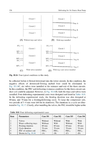
Circuit 1 Circuit 1
Tray A
Circuit 2 Circuit 2
Tray B
Circuit 3 Circuit 3
Tray C
(A) Without trays and valves (B) With trays installed
SV 1 SV 1
Circuit 1 Circuit 1
MV 1 MV 1
SV 2 SV 2 Tray A
Circuit 2 Circuit 2
MV 2 MV 2
Tray B
SV 3 SV 3
Circuit 3 Circuit 3
MV 3 MV 3
Tray C
(C) With valves installed (D) With trays and valves installed
Fig. 10.16 Four typical conditions in this study.
be collected before it flowed downward into the lower circuits. In this condition, the
negative effects of downward-flowing melted frost could be eliminated. In
Fig. 10.16C, six valves were installed at the entrance and exit of the three circuits.
In this condition, the FEC and defrosting evenness condition for the three-circuit out-
door coil could be adjusted. However, in Fig. 10.16D, both the trays and valves were
installed. Four defrosting experimental cases were designed and listed in Table 10.8.
In the defrosting experimental study, the frosting duration was also designed at
60 min, and 70 min for a frosting/defrosting cycle. To keep the compressor safe,
two periods of 3–4 min were left for its shutdown. The durations in a cycle are illus-
trated in Fig. 10.17. Clearly, after installing the valves, the FEC should be higher at the
Table 10.8 Four defrosting experimental cases
Item Parameters Case D1 Case D2 Case D3 Case D4
1 Valves Without Without With With
2 Water-collecting trays Without With Without With
3 Frosting duration 60 min 60 min 60 min 60 min
4 Cycle duration 70 min 70 min 70 min 70 min
5 FEC of outdoor coil FEC 3 FEC 3 FEC 4 FEC 4
6 Shown in Fig. 10.16 (A) (B) (C) (D)