
Page 110 - Dynamic Vision for Perception and Control of Motion
P. 110
3 Subjects and Subject Classes
94
Direction of inertial a x -measurement to be fastened to the vehi-
Axle distance a z y-direction normal
to the image plane cle body (e.g., by seat
to the left of driving
Center of gravity cg direction belts or nets). On most re-
F b íI y ș ˚˚ í ǻV x alistic surfaces, decelera-
ǻV f m·a x f tion will certainly be
í a x íș
h cg smaller. In normal traffic
+ +
conditions, a realized fric-
tion coefficient of ȝ = 0.5
F additional spring (f z ·ǻz) and F
br bf
˚
damper (d ·ǻz) forces is considered harsh brak-
ing (deceleration a x §í5
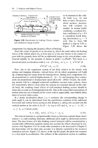
Figure 3.20. Deceleration by braking: Forces, torques,
m/s², that is, from 100
and orientation change in pitch
km/h to a stop in 5.56 s).
Figure 3.20 shows the
components for judging the dynamic effects of braking.
Since the center of gravity is at elevation h cg above the point where the braking
forces of the wheels attack (F bf at front and F br at the rear wheels in the contact re-
gion with the ground), there will be an additional torque in the vertical plane, coun-
teracted initially by the moment of inertia in pitch (íI y·d²ș/dt²). This leads to a
2
m a
downward pitch acceleration (with I y = m · i y²) via h x I T / dt 2 of
d
y
cg
2
2
d T / dt 2 h cg a x / . (3.24)
i
y
Now, due to the suspension system of the body relative to the wheels with
springs and damping elements, vertical forces ǻV f in wheel suspension will build
up, counteracting the torque from the braking forces. Spring force components ǻV f
are proportional to vertical displacements (f z · ǻz ~ ș), and damping force compo-
nents are proportional to displacement speed (d(ǻz)/dt ~ dș/dt). Usually, the result-
ing motion will be a damped rotational oscillation (second–order system). Since
this immediately affects vision when the cameras are mounted directly on the vehi-
cle body, the resulting visual effects of (self-initiated) braking actions should be
taken into account at all interpretation levels. This is the reason that expectations of
motion behavior are so beneficial for vision with its appreciable, unavoidable delay
times of several video cycles.
In a steady deceleration phase (ía x = constant), the corresponding change in
pitch angle ș b can be determined from the equilibrium condition of the additional
horizontal and vertical forces acting at axle distance a, taking into account that the
m a '
vertical motion at the axles is ș b·a/2 = ǻz (cg at a/2) and h x a V
f
cg
z ș a /2 which yields
af
b
ș =[2h cg m /( f a 2 )] a x p a x (3.25)
z
b
b
The term in brackets is a proportionality factor p b between constant linear decel-
eration (ía x) and resulting stationary additional pitch angle ș b (downward positive
here). The time history of ș after braking control initiation will be constrained by a
second-order differential equation taking into account the effects discussed in con-
nection with Equation 3.24. In visual state estimation to be discussed in Chapter 9,
this knowledge will be taken into account; it is directly exploited in the recursive
estimation process. Figure 3.21 shows, in the top left graph, the pitch rate response
to a step input in acceleration. The softness of the suspension system in combina-