
Page 111 - Dynamic Vision for Perception and Control of Motion
P. 111
3.4 Behavioral Capabilities for Locomotion 95
tion with inertia of the body lead to the oscillation extending to almost 2 seconds
after the change in control input. The general second-order dynamic model for an
arbitrary excitation f [a x (t)] for braking is given by
d T 2 / dt 2 D d T / dt f T [ f a t()]. (3.26)
Sp x
/dt pitch rate dș/dt d/d cg - motion above the ground
0
0 dz/dt
Time in seconds Time in seconds
2 3 4 5 6 7 8 2 3 4 5 6 7 8
Step input of moment M Y around Step input of moment M Y around
y-axis due to acceleration y-axis due to acceleration
Road height h step input Road height h step input
2 3 4 5 6 7 8 2 3 4 5 6 7 8
Time in seconds Time in seconds
Figure 3.21. Simulation of vehicle suspension model: Pitch rate (top left) and heave re-
sponse (top right) of ground vehicle suspension after step input in acceleration (center)
as well as the height profile of the ground (bottom)
Since the eigenfrequency of the vehicle does not change over time and since it is
characteristic of the vehicle in a given loading state, this oscillation over as many
as 50 video cycles can be expected for a certain control input. This alleviates image
sequence interpretation when properly represented in the perception system.
Pitching motion due to partial loss of wheel support: This topic would also fit
under “vertical curvature effects” (above). However, the eigenmotion in pitch after
a step input in wheel support may be understood more easily after the step input in
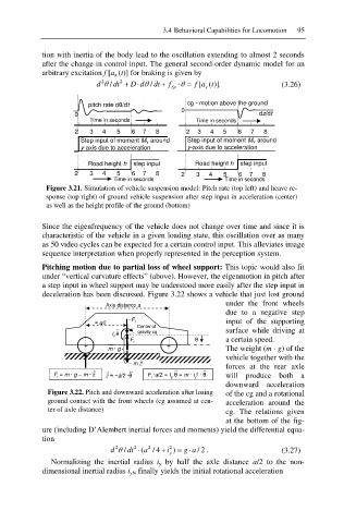
deceleration has been discussed. Figure 3.22 shows a vehicle that just lost ground
under the front wheels
Axle distance a
due to a negative step
íF
§ a/2 r input of the supporting
Center of
I y ș ˚˚ gravity cg surface while driving at
F ș a certain speed.
+ r +
m · g The weight (m · g) of the
vehicle together with the
– mz ˚˚
forces at the rear axle
˚˚
F = m · g – m ·z ˚˚ ˚˚ ˚˚ F ·a/2 = I ș = m · i ²· ș ˚˚ will produce both a
z §ía/2 ·ș
r r y y
downward acceleration
Figure 3.22. Pitch and downward acceleration after losing of the cg and a rotational
ground contact with the front wheels (cg assumed at cen- acceleration around the
ter of axle distance) cg. The relations given
at the bottom of the fig-
ure (including D’Alembert inertial forces and moments) yield the differential equa-
tion
d 2 / dt T 2 (a 2 / 4 i 2 ) g 2 / a . (3.27)
y
Normalizing the inertial radius i y by half the axle distance a/2 to the non-
dimensional inertial radius i yN finally yields the initial rotational acceleration