
Page 113 - Dynamic Vision for Perception and Control of Motion
P. 113
3.4 Behavioral Capabilities for Locomotion 97
For the data mentioned, the lane change time is T LC = 2.68 seconds, and the
maximum speed at the center of the idealized maneuver is v ymaxLCi {t = T LC/2} =
2.68 m/s. Since Ackermann steering is nonholonomic, real cars cannot perform this
type of lane change maneuver; however, it is nice as a reference for realizable ma-
neuvers to be discussed in the following. For a y = 4 m/s², lane change time would
be 1.9 seconds and maximum lateral speed v y (T LC/2) = 3.8 m/s.
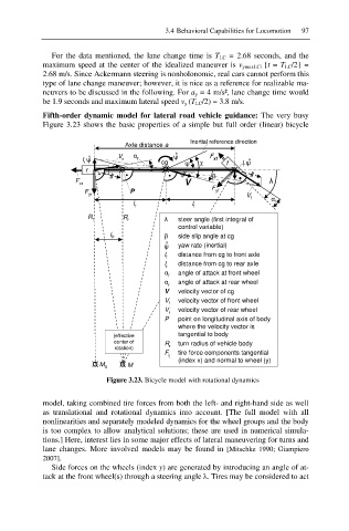
Fifth-order dynamic model for lateral road vehicle guidance: The very busy
Figure 3.23 shows the basic properties of a simple but full order (linear) bicycle
Inertial reference direction
Axle distance a
°
l ȥ V r Į r cg ȥ ° ȥ Ȥ F xf f l ȥ °
r
r ¤ ¤ ¤ f
ȕ
F V Ȝ
xr
F
F yr P yf V
l r l f f Į f
R r R r Ȝ steer angle (first integral of
control variable)
l P ȕ side slip angle at cg
°
ȥ yaw rate (inertial)
l f distance from cg to front axle
l distance from cg to rear axle
r
Į f angle of attack at front wheel
Į angle of attack at rear wheel
r
V velocity vector of cg
V f velocity vector of front wheel
V velocity vector of rear wheel
r
P point on longitudinal axis of body
where the velocity vector is
(effective tangential to body
center of R turn radius of vehicle body
rotation) r
F ij tire force components tangential
(index x) and normal to wheel (y)
¤ M 0 ¤ M
Figure 3.23. Bicycle model with rotational dynamics
model, taking combined tire forces from both the left- and right-hand side as well
as translational and rotational dynamics into account. [The full model with all
nonlinearities and separately modeled dynamics for the wheel groups and the body
is too complex to allow analytical solutions; these are used in numerical simula-
tions.] Here, interest lies in some major effects of lateral maneuvering for turns and
lane changes. More involved models may be found in [Mitschke 1990; Giampiero
2007].
Side forces on the wheels (index y) are generated by introducing an angle of at-
tack at the front wheel(s) through a steering angle Ȝ. Tires may be considered to act