
Page 185 - Electrical Properties of Materials
P. 185
Rectification 167
If the p-side is made positive the potential barrier is reduced, and we talk of
forward bias. The opposite case is known as reverse bias; the p-side is then
negative, and the potential barrier is increased.
It is fairly obvious qualitatively that the number of electrons flowing from
left to right is not affected in either case. The same number of electrons will
still roll down the hill as in equilibrium. But the flow of electrons from right to
left is seriously affected. For reverse bias it will be reduced and for forward bias
it will significantly increase. So we can see qualitatively that the total current
flowing for a voltage U 1 will differ from the current flowing at a voltage –U 1 .
This is what is meant by rectification.
It is not difficult to derive the mathematical relationships; we have practic-
ally everything ready. The current from left to right is the same; let us denote
it by I 0 . The current from right to left may be obtained by putting e(U 0 – U 1 )
in place of eU 0 in eqn (9.14). [This is because we now want the number of
electrons having energies in excess of e(U 0 – U 1 ), etc.] At U 1 = 0, this current
is equal to I 0 and increases exponentially with U 1 ; that is
I e(right to left) = I 0 exp(eU 1 /k B T). (9.16)
Hence the total current Above about 1 volt bias, the final
‘–1’ in the rectifier equation can be
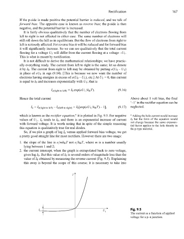
I e = I e(right to left) – I e(left to right) = I 0 [exp(eU 1 /k B T) – 1], (9.17) neglected.
which is known as the rectifier equation; it is plotted in Fig. 9.5. For negative ∗ Adding the hole current would increase
∗
values of U 1 , I e tends to I 0 , and there is an exponential increase of current I 0 but the form of the equation would
not change because the same exponen-
with forward voltage. It is worth noting that in spite of the simple reasoning
tial factor applies to the hole density in
this equation is qualitatively true for real diodes. the p-type material.
So, if we plot a graph of log I e versus applied forward bias voltage, we get
a pretty good straight line for most rectifiers. However there are two snags:
1. the slope of the line is e/mk B T not e/k B T, where m is a number usually
lying between 1 and 2;
2. the current intercept, when the graph is extrapolated back to zero voltage,
gives log I 0 . But this value of I 0 is several orders of magnitude less than the
value of I 0 obtained by measuring the reverse current (Fig. 9.5). Explaining
this away is beyond the scope of this course; it is necessary to take into
I
I U Fig. 9.5
0
1
The current as a function of applied
voltage for a p–n junction.