
Page 187 - Electrical Properties of Materials
P. 187
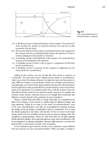
Injection                         169

                                                            Total current
                                  (iii)
                                                        (vi)
                      p                        (iv)             n


                        (v)              (ii)                     (i)        Fig. 9.7
                                                                             The current distribution in a
                                                                             forward biased p–n junction.


             (ii) A declining current of injected electrons in the p-region. The current de-
                clines because the number of electrons becomes less and less as they
                recombine with the holes.
            (iii) The current of holes in the p-region to provide the holes to be injected into
                the n-region. We have not discussed this because the injection of holes is
                entirely analogous to the injection of electrons.
             (iv) A declining current of injected holes in the n-region. The current declines
                because of recombination with electrons.
             (v) A declining current of holes in the p-region to compensate for the holes
                lost by recombination.
             (vi) A declining current of electrons in the n-region to compensate for the
                electrons lost by recombination.

               Adding up the currents, you can see that the total current is constant, as
            it should be. The discussion above includes all the effects of recombination,
            which occur when the distance between the depletion layer and the contacts is
            long. Often the distance is much shorter. In this case a simpler model (known,
            unsurprisingly, as the short diode approximation) may be used. Recombination
            may be neglected, on the grounds that the injected minority carriers do not have
            much of an opportunity to recombine before they reach the contacts. Since the
            individual currents carried by the injected carriers must now be constant, the
            minority carrier density variations must now be straight lines (remember that
            diffusion currents depend on the gradients of carrier densities).
               When is a diode short and when is it long? Generally it is considered to be
            short if the distance to the contacts is smaller than the diffusion length, and
            long otherwise. When do we want it to be short? In microelectronics, most
            of the time. Recombination will often be accompanied by heating, because
            the energy given up during recombination must go somewhere. If it is used
            for phonon generation, the device will run hot. At the very least it will waste
            energy, and it will very probably not last as long as a device running cold. The
            exception is optoelectronics, which we will cover later on. In light emitting
            diodes and laser diodes, direct-gap materials are used, and recombination will
            be accompanied by photon generation. Because light emission is exactly the
            desired effect, a long diode is exactly what is required.
               Let me emphasize again that the current in a p–n junction is quite different
            from the currents you have encountered before. When you apply a voltage to