
Page 206 - Electrical Properties of Materials
P. 206
188 Principles of semiconductor devices
phase difference between voltage and current, at least for a certain frequency
range. But this is nothing more than a frequency-dependent negative resistance.
Putting the diode in a cavity, the oscillator is ready.
9.13 Varactor diodes
As I have mentioned above, and shown mathematically in eqn (9.21), the capa-
citance of a reverse-biased p–n junction is voltage dependent. In other words
the capacitance is variable, and that is what the name ‘varactor’ seems to
stand for.
Varactor diodes are p–n junctions designed for variable capacitance opera-
tion. Is a variable capacitance good for anything? Yes, it is the basis of the
so-called ‘parametric amplifier’. How does a parametric amplifier work? This
is really a circuit problem, but I had better explain its operation briefly.
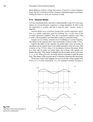
Imagine just an ordinary resonant circuit oscillating at a certain frequency.
The charge on the capacitor then varies sinusoidally as shown in Fig. 9.31(a).
Suppose the plates of the capacitor are pulled apart when Q reaches its
maximum and are pushed back to the initial separation when Q is zero. This
is shown in Fig. 9.31(b), where d is the distance between the plates. When
Q is finite and the plates are pulled apart, one is doing work against cou-
lombic attraction. Thus, energy is pumped into the resonant circuit at the times
t 1 , t 3 , t 5 , etc. When Q is zero, no energy need be expended to push the plates
back. The energy of the resonant circuit is therefore monotonically increasing.
To see more clearly what happens, let us try to plot the voltage against time.
From t 0 to t 1 it varies sinusoidally. At t 1 the separation between the plates is
(a)
Q
t
d
(b)
t t t t t t
t 0 1 2 3 4 5 6
(c)
U t
(d)
Fig. 9.31
Illustration of the basic principles of Q t
parametric amplification.