
Page 428 - Electrical Properties of Materials
P. 428
410 Artificial materials or metamaterials
The expression for the inductance of a wire may be obtained from tables as
μ 0 2 3
L w = ln – . (15.9)
2π r w 4
As an example, let us take = 6 mm and r w = 0.03 mm. The resultant plasma
frequency may be calculated from eqns (15.7) and (15.9) to be 8.73 GHz, not
far from the measured value of 9.5 GHz.
15.5 Resonant elements for metamaterials
(a) (b) The wire elements in the previous section are not resonant. They are useful
because they can provide a negative dielectric constant at frequencies below
the equivalent plasma frequency, which can be adjusted by choosing the period
and the diameter of the wire. However, most metamaterial elements are reson-
ant, and then the problem arises of how to make them small. It is not trivial to
g g
satisfy the requirement for the elements to be resonant and at the same time
to be small relative to the wavelength. When we think of an electromagnetic
resonator, the one that first to come to mind is probably the Fabry–Pérot reson-
ator used in lasers. This consists of two parallel mirrors a distance D apart, as
has been discussed several times (see e.g. Fig. 12.4). Resonance occurs when
h D is equal to an integral (very large) number of wavelengths. It is then easy
to imagine a wave trapped between the two mirrors just bouncing back and
forth between them. But that resonator is very big. If we want a resonator to
wcw w cw
(c) be small relative to the wavelength, this can easily be realized by lumped cir-
cuit elements, all we need is an inductance L and a capacitance C. With a
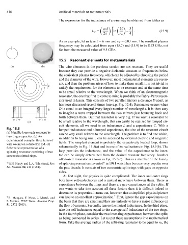
Fig. 15.5 lumped inductance and a lumped capacitance, the size of the resonant circuit
(a) Metallic loop made resonant by can be very small relative to the wavelength. The problem is to find one which,
inserting a capacitor. (b) An
in addition to being small, can be accessed by external electric and magnetic
experimental example: three turns of
fields. The simplest element is probably the capacitively loaded loop, shown
wire wound on a dielectric rod. (c)
schematically in Fig. 15.5(a) and in one of its realizations in Fig. 15.5(b). The
Schematic representation of a
split-ring resonator consisting of two loop provides the inductance, and the value of the capacitance to be inser-
concentric slotted rings. ted can be simply determined from the desired resonant frequency. Another
often-used resonator is shown in Fig. 15.5(c). This is a member of the family
∗
∗ W.H. Hardy and L.A. Whitehead, Rev. of split-ring resonators invented in 1981 which has become very popular over
Sci. Instrum. 52, 213 (1981). the past decade. It consists of two concentric split rings with gaps on opposite
sides.
At first sight, the physics is quite complicated. The inner and outer rings
both have self-inductances and a mutual inductance between them. There is
capacitance between the rings and there are gap capacitances at the splits. If
one wants to take into account all these factors then it is difficult indeed to
determine its properties. It turns out, however, that a simplified physical picture
†
† R. Marques, F. Mesa, J. Martel, and can lead to an excellent approximation. First, ignore the gap capacitances on
F. Medina, IEEE Trans. Antenna Prop. the basis that they are small and they are unlikely to have a major influence on
51, 2572 (2003). the flow of currents. Secondly, ignore the mutual inductance. In the third place,
take the self-inductance equal to the average self-inductance of the two rings.
In the fourth place, consider the two inter-ring capacitances between the splits
as being connected in series. Let us put these assumptions into mathematical
form. Take the average radius of the split-ring resonator to be equal to r 0 ,the