
Page 429 - Electrical Properties of Materials
P. 429
Polarizability of a current-carrying resonant loop 411
d c g
w
L d
D c w r 2
b h r 3 r 1
f g r 4
b s t ed c
(a) (b) (c) (d) (e)
w t
r r
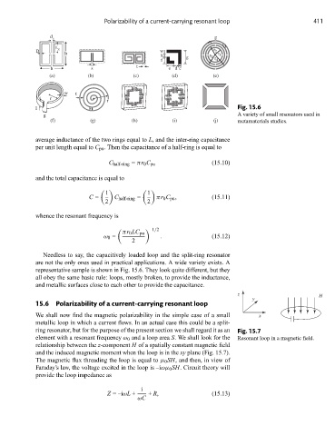
l s Fig. 15.6
g A variety of small resonators used in
(f) (g) (h) (i) (j) metamaterials studies.
average inductance of the two rings equal to L, and the inter-ring capacitance
per unit length equal to C pu . Then the capacitance of a half-ring is equal to
C half-ring = πr 0 C pu (15.10)
and the total capacitance is equal to
1 1
C = C half-ring = πr 0 C pu , (15.11)
2 2
whence the resonant frequency is
–1/2
πr 0 LC pu
ω 0 = . (15.12)
2
Needless to say, the capacitively loaded loop and the split-ring resonator
are not the only ones used in practical applications. A wide variety exists. A
representative sample is shown in Fig. 15.6. They look quite different, but they
all obey the same basic rule: loops, mostly broken, to provide the inductance,
and metallic surfaces close to each other to provide the capacitance.
z H
y
15.6 Polarizability of a current-carrying resonant loop
We shall now find the magnetic polarizability in the simple case of a small x
metallic loop in which a current flows. In an actual case this could be a split-
ring resonator, but for the purpose of the present section we shall regard it as an Fig. 15.7
element with a resonant frequency ω 0 and a loop area S. We shall look for the Resonant loop in a magnetic field.
relationship between the z-component H of a spatially constant magnetic field
and the induced magnetic moment when the loop is in the xy plane (Fig. 15.7).
The magnetic flux threading the loop is equal to μ 0 SH, and then, in view of
Faraday’s law, the voltage excited in the loop is –iωμ 0 SH. Circuit theory will
provide the loop impedance as
i
Z =–iωL + + R, (15.13)
ωC