Page 53 - Embedded Microprocessor Systems Real World Design
P. 53

In normally-not-ready systems, the peripheral must generate an ACK to indicate
                  that the transfer is complete. In actual systems, the peripheral itself usually does
                  not introduce the wait states. This is normally done by the logic that controls access
                  to the peripheral device, which times wait or ACK assertions and makes sure that
                  they are asserted only when the correct peripheral is accessed. Some peripherals
                  (particularly those  designed for  the  68000 family) generate ACK  internally  and
                  need no external logic for this function.


                  Memory


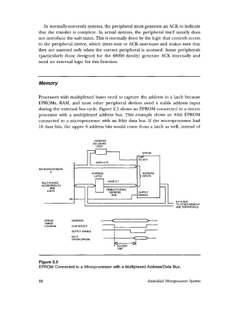
                  Processors with multiplexed buses need to capture the address in a latch because
                  EPROMs, RAM, and most  other  peripheral  devices need  a  stable address input
                  during the external bus cycle. Figure 2.5 shows an EPROM connected to a micro-
                  processor with  a multiplexed  address bus. This example shows an &bit EPROM
                  connected to a microprocessor with an &bit data bus. If  the microprocessor had
                  16 data bits, the upper 8 address bits would come from a latch as well, instead of


                                           ADDRESS
                                          DECODING
                                           LOGIC

                                                              ....
                                                                        I
                  MICROPROCESSOR
                       IC
                                          ADDRESS
                                           -
                                           LATCH
                                                 ADDR 0:7
                    MULTIPLEXED
                    ADDRESWDATA                                         I
                       BUS
                      8 BITS                    DEMULTIPLEXED
                                                 ADDRESS
                               -RC
                                                                               DATA BUS
                                                                               TO OTHER MEMORY
                                                                               AND PERIPHERALS
                     EPROM       ADDRESS
                     TIMING
                     DIAGRAM     CHIP SELECT
                                                    I
                                 OUTPUT ENABLE      I     7      I
                                                    I
                                 DATA
                                 (FROM EPROM)   P
                                                             I
                                                    RccEss
                                                     TIME
                  Figure 2.5
                  EPROM Connected to a Microprocessor with a Multiplexed Address/Data Bus.


                  38                                              Embedded Microprocessor Systems
   48   49   50   51   52   53   54   55   56   57   58