
Page 287 - Engineering Digital Design
P. 287
258 CHAPTER 6 / NONARITHMETIC COMBINATIONAL LOGIC DEVICES
Gray Binary Gray Binary
1
1
1
A B C D A B C' D 1 AB C D A B' C' D'
0 0 0 0 0 0 0 0 1 0 0 0 1 1 1 1
0 0 0 1 0 0 0 1 1 0 0 1 1 1 1 0
0 0 1 0 0 0 1 1 1 0 1 0 1 1 0 0
0 0 1 1 0 0 1 0 1 0 1 1 1 1 0 1
0 1 0 0 0 1 1 1 1 1 0 0 1 0 0 0
0 1 0 1 0 1 1 0 1 1 0 1 1 0 0 1
0 1 1 0 0 1 0 0 1 1 1 0 1 0 1 1
0 1 1 1 0 1 0 1 1 1 1 1 1 0 1 0
(a)
By inspection
A' =
(b) (c)
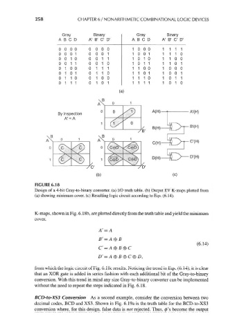
FIGURE 6.18
Design of a 4-bit Gray-to-binary converter, (a) I/O truth table, (b) Output EV K-maps plotted from
(a) showing minimum cover, (c) Resulting logic circuit according to Eqs. (6.14).
K-maps, shown in Fig. 6. 18b, are plotted directly from the truth table and yield the minimum
cover,
A' = A
B' = A®B
(6.14)
c = A e B e c
from which the logic circuit of Fig. 6. 1 8c results. Noticing the trend in Eqs. (6. 14), it is clear
that an XOR gate is added in series fashion with each additional bit of the Gray-to-binary
conversion. With this trend in mind any size Gray-to-binary converter can be implemented
without the need to repeat the steps indicated in Fig. 6.18.
BCD-to-XS3 Conversion As a second example, consider the conversion between two
decimal codes, BCD and XS3. Shown in Fig. 6.19a is the truth table for the BCD-to-XS3
conversion where, for this design, false data is not rejected. Thus, 0's become the output