
Page 285 - Engineering Digital Design
P. 285
256 CHAPTER 6 / NONARITHMETIC COMBINATIONAL LOGIC DEVICES
(GS,)
EI(L) -c El, GS, D
EI 1 EI 0 I 5 I 4 I 3 I 2 I, I 0 Y 2 Y, Y 0 E0 1 E0 0 Y 2(L)
D
0 O X X X X X X o o o o o i 5_ 3(L)-4-c 1
PE/
Y o
1 0 1 X X X X X 1 1 1 0 0
K>i >-| -4~X^
1 0 0 1 X X X X 1 1 0 0 0 —q_^
1
1 0 0 0 1 X X X 1 0 1 0 0 | 1
1 1 0 0 0 1 X X 0 1 1 1 0 —<sr~^
L-c EL -d j°- Y 0(D
GS n
1 1 0 0 0 0 1 X 0 1 0 1 0 •_ig ^"-'Q T '
1 1 0 0 0 0 0 1 0 0 1 1 0 I 2 . 0 (L)^-C Y
PEo ' 0
°Y O
1 1 0 0 0 0 0 0 0 0 0 1 1
EO O D ~
Y -T IrrtalAvant innnt (\r\nir fl r»r Innir 1^
(a) (b)
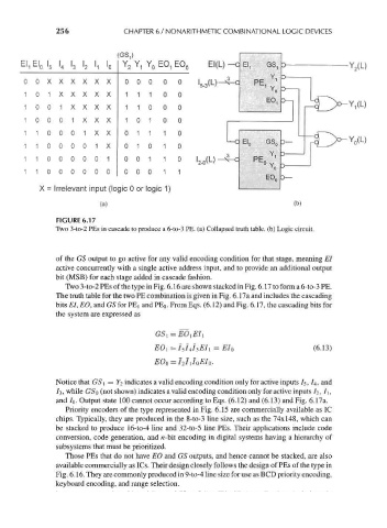
FIGURE 6.17
Two 3-to-2 PEs in cascade to produce a 6-to-3 PE. (a) Collapsed truth table, (b) Logic circuit.
of the GS output to go active for any valid encoding condition for that stage, meaning El
active concurrently with a single active address input, and to provide an additional output
bit (MSB) for each stage added in cascade fashion.
Two 3-to-2 PEs of the type in Fig. 6. 16 are shown stacked in Fig. 6. 17 to form a 6-to-3 PE.
The truth table for the two PE combination is given in Fig. 6. 17a and includes the cascading
bits El, EO, and GS for PE] and PE 0. From Eqs. (6.12) and Fig. 6. 17, the cascading bits for
the system are expressed as
(6.13)
EOi = / 57 4/3^/i = EI 0
E0 0 = I 2I J 0EI 0.
Notice that GS\ = Y 2 indicates a valid encoding condition only for active inputs I 5 , 7 4, and
/3, while GSo (not shown) indicates a valid encoding condition only for active inputs /2 , /i ,
and IQ. Output state 100 cannot occur according to Eqs. (6.12) and (6.13) and Fig. 6.17a.
Priority encoders of the type represented in Fig. 6.15 are commercially available as 1C
chips. Typically, they are produced in the 8-to-3 line size, such as the 74x148, which can
be stacked to produce 16-to-4 line and 32-to-5 line PEs. Their applications include code
conversion, code generation, and n-bit encoding in digital systems having a hierarchy of
subsystems that must be prioritized.
Those PEs that do not have EO and GS outputs, and hence cannot be stacked, are also
available commercially as ICs. Their design closely follows the design of PEs of the type in
Fig. 6. 16. They are commonly produced in 9-to-4 line size for use as BCD priority encoding,
keyboard encoding, and range selection.