
Page 281 - Engineering Digital Design
P. 281
252 CHAPTER 6 / NONARITHMETIC COMBINATIONAL LOGIC DEVICES
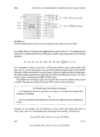
F(H) = Im(1,3,4,7) (H)
C(H)
B(H) 3-to-8 Y G(H) = nM(2,3,5,6) (H)
, Decoder
A(H)-
FIGURE 6.13
Decoder implementations of Eqs. (6.10) assuming inputs and outputs are all active high.
active high, these two functions are implemented as given in Fig. 6.13. To understand why
function G is implemented with an AND gate, consider what is generated by the ANDing
operation:
G = m 2-m 3-m5-m 6 = M 2- M 2- M 5-M 6 = Y\ M(2, 3, 5, 6).
If it is desirable to issue G active low, a NAND gate would be used in place of the AND
gate. Or if F is to be issued active low, an AND would be needed in place of the NAND.
Actually, to fully understand the versatile nature of function implementation with decoders,
the reader should experiment by replacing the NAND and AND gates in Fig. 6.13 with a
variety of gates, including treed XOR and EQV gates.
The problem of mixed-logic inputs can be dealt with in a manner similar to those issued
to MUXs. The rules are similar to those for MUXs and are stated as follows:
For Mixed-Logic Data Inputs to Decoders
(1) Complement the bit of any active low input to a decoder and renumber the
minterms accordingly.
or
(2) Use an inverter on the input line of an active low input and do not complement
the bit.
Consider, as an example, the two functions of Eqs. (6.10) with inputs that arrive as
A(H), B(L}, and C(L). Functionally, the mixed-logic forms of Eqs. (6.10) become
), B(L), C(L}} = F SOp[A, B, C](H)
and (6.11)
), B(L), C(L)] = G POS[A, B,