
Page 277 - Engineering Digital Design
P. 277
248 CHAPTER 6 / NONARITHMETIC COMBINATIONAL LOGIC DEVICES
KL)
i) (i UG
; [
^~i> 1 4-10-1 V Y(H)
C -D 1 r^N MUX O-Y(L)
—^L^~ 2
Ceo C + D -+- H
'3
Y S
Si o
(a) (b) 1 \
A(H) B(L)
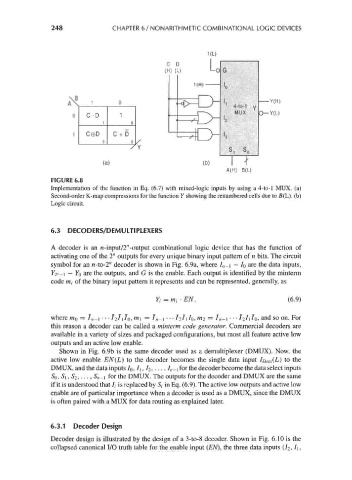
FIGURE 6.8
Implementation of the function in Eq. (6.7) with mixed-logic inputs by using a 4-to-l MUX. (a)
Second-order K-map compressions for the function Y showing the renumbered cells due to 5(L). (b)
Logic circuit.
6.3 DECODERS/DEMULTIPLEXERS
A decoder is an n -input/2" -output combinational logic device that has the function of
activating one of the 2" outputs for every unique binary input pattern of n bits. The circuit
symbol for an n-to-2" decoder is shown in Fig. 6.9a, where I n-\ — IQ are the data inputs,
72" -i — YQ are the outputs, and G is the enable. Each output is identified by the minterm
code m( of the binary input pattern it represents and can be represented, generally, as
Yi = mi • EN, (6.9)
where mo = l n-\ • • • hlilo, m\ = I n-\ • • • /2/i/o, ^2 = I n-\ • • • 72/i/o, and so on. For
this reason a decoder can be called a minterm code generator. Commercial decoders are
available in a variety of sizes and packaged configurations, but most all feature active low
outputs and an active low enable.
Shown in Fig. 6.9b is the same decoder used as a demultiplexer (DMUX). Now, the
active low enable EN(L) to the decoder becomes the single data input iData(L) to the
DMUX, and the data inputs 7 0, I\, /2, . . . , 7 n _i for the decoder become the data select inputs
SQ, S\ , $2, . . . , S n-i for the DMUX. The outputs for the decoder and DMUX are the same
if it is understood that 7, is replaced by Sj in Eq. (6.9). The active low outputs and active low
enable are of particular importance when a decoder is used as a DMUX, since the DMUX
is often paired with a MUX for data routing as explained later.
6.3.1 Decoder Design
Decoder design is illustrated by the design of a 3-to-8 decoder. Shown in Fig. 6.10 is the
collapsed canonical I/O truth table for the enable input (EN), the three data inputs (7 2, I\,