
Page 274 - Engineering Digital Design
P. 274
6.2 MULTIPLEXERS 245
S 2 .i.o(H)
EN(L)
S 43(H)
Y(L) Y(H)
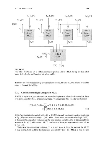
FIGURE 6.5
Four 8-to-l MUXs and a 4-to-l MUX combine to produce a 32-to-l MUX having five data select
inputs 84, 83, 82, S], and SQ and an active low enable.
that there are two independently operated enable inputs, \G and 2G, that enable or disable
either or both of the MUXs.
6.2.2 Combinational Logic Design with MUXs
A MUX is a function generator and can be used to implement a function in canonical form
or in compressed (reduced or minimum) form. To understand this, consider the function
Y(A,B,C, D) = ]Tm(3,4, 5,6,7, 9, 10, 12, 14, 15)
= ["[M(0, 1,2, 8, 11,13). (6.7)
If this function is implemented with a 16-to-l MUX, then all inputs representing minterms
in Eq. (6.7) are connected to logic 1 (HV) while all maxterms are connected to logic 0 (LV).
In this case the data select variables are the four function variables. But if it is desirable to
implement Eq. (6.7) with a 4-to-l MUX, two levels of K-map compression are needed, as
in Fig. 6.7b.
Notice that the data select variables, S\ — A and SQ = B, form the axes of the MUX
K-map in Fig. 6.7b and that the functions generated by the 4-to-l MUX in Fig. 6.7 are