
Page 275 - Engineering Digital Design
P. 275
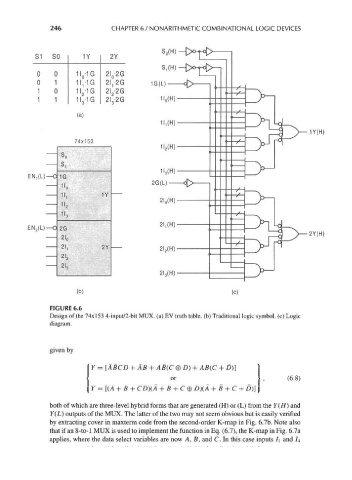
246              CHAPTER 6 / NONARITHMETIC COMBINATIONAL LOGIC DEVICES


                                                    S 0(H)
                bl   £>U     i y     ZY

                0    0     11 -1G   2L-2G
                             0       0
                0    1     11,-IG   21^20
                1    0     1I 2 -1G  2I 2-2G
                1    1     1I 3 -1G  2I 3-2G

                           (a)


                                                                    ___                      1Y(H)
                                                                    Ti  l  I      I  M  -^
                           74x153


              EN^L)-   1G
                       I'o
                       11,         1Y
                       1I 2
                       11,
             EN 2(L)   2G
                                                                                             2Y(H)
                                                                    rrcn—\ i HdK^
                                  2Y
                       2I 2
                       21 3


                           (b)                                         (c)
                    FIGURE 6.6
                    Design of the 74x153 4-input/2-bit MUX. (a) EV truth table, (b) Traditional logic symbol, (c) Logic
                    diagram.


                    given by
                                Y = [ABCD + AB + AB(C 0 D) + AB(C + D)]
                                                      or                                (6.8)
                                Y = [(A + B + CD)(A + B + C® D)(A + B + C + D)]

                    both of which are three-level hybrid forms that are generated (H) or (L) from the Y(H) and
                    Y(L) outputs of the MUX. The latter of the two may not seem obvious but is easily verified
                    by extracting cover in maxterm code from the second-order K-map in Fig. 6.7b. Note also
                    that if an 8-to-l MUX is used to implement the function in Eq. (6.7), the K-map in Fig. 6.7a
                    applies, where the data select variables are now A, B, and C. In this case inputs I\ and /4